HPS GSRD User Guide for the Agilex™ 3 C-Series Development Kit
Introduction
GSRD Overview
The Golden System Reference Design (GSRD) is a reference design running on the Agilex™ 3 C-Series Development Kit.
The GSRD is comprised of the following components:
- Golden Hardware Reference Design (GHRD)
- Reference HPS software including:
- Arm Trusted Firmware
- U-Boot
- Linux Kernel
- Linux Drivers
- Sample Applications
Prerequisites
The following are required to be able to fully exercise the Agilex 3 FPGA and SoC C-Series Development Kit GSRD:
- Altera® Agilex™ 3 FPGA and SoC C-Series Development Kit, ordering code DK-A3W135BM16AEA. Refer to board documentation for more information about the development kit.
-
Host PC with:
- 64 GB of RAM. Less will be fine for only exercising the binaries, and not rebuilding the GSRD.
- Linux OS installed. Ubuntu 22.04LTS was used to create this page, other versions and distributions may work too
- Serial terminal (for example GtkTerm or Minicom on Linux and TeraTerm or PuTTY on Windows)
- Altera® Quartus® Prime Pro Edition Version 25.1.1
- TFTP server. This used to download the eMMC binaries to board to be flashed by U-Boot
- Local Ethernet network, with DHCP server
- Internet connection. For downloading the files, especially when rebuilding the GSRD.
Prebuilt Binaries
The Agilex™ 3 FPGA and SoC C-Series Development Kit GSRD binaries are located at https://releases.rocketboards.org/2025.08/:
| Boot Source | Link |
|---|---|
| SD Card | https://releases.rocketboards.org/2025.08/gsrd/agilex3_gsrd |
| QSPI | https://releases.rocketboards.org/2025.08/qspi/agilex3_qspi |
Component Versions
Altera® Quartus® Prime Pro Edition Version 25.1.1 and the following software component versions integrate the 25.1.1 release.
Note: Regarding the GHRD components in the following table, only the device-specific GHRD is used in this page.
| Component | Location | Branch | Commit ID/Tag |
|---|---|---|---|
| Agilex 3 GHRD | https://github.com/altera-fpga/agilex3c-ed-gsrd | main | QPDS25.1.1_REL_GSRD_PR |
| Agilex 5 GHRD | https://github.com/altera-fpga/agilex5e-ed-gsrd | main | QPDS25.1.1_REL_GSRD_PR |
| Agilex 7 GHRD | https://github.com/altera-fpga/agilex7f-ed-gsrd | main | QPDS25.1.1_REL_GSRD_PR |
| Stratix 10 GHRD | https://github.com/altera-fpga/stratix10-ed-gsrd | main | QPDS25.1.1_REL_GSRD_PR |
| Arria 10 GHRD | https://github.com/altera-fpga/arria10-ed-gsrd | main | QPDS25.1.1_REL_GSRD_PR |
| Linux | https://github.com/altera-fpga/linux-socfpga | socfpga-6.12.19-lts | QPDS25.1.1_REL_GSRD_PR |
| Arm Trusted Firmware | https://github.com/altera-fpga/arm-trusted-firmware | socfpga_v2.12.1 | QPDS25.1.1_REL_GSRD_PR |
| U-Boot | https://github.com/altera-fpga/u-boot-socfpga | socfpga_v2025.04 | QPDS25.1.1_REL_GSRD_PR |
| Yocto Project | https://git.yoctoproject.org/poky | walnascar | latest |
| Yocto Project: meta-intel-fpga | https://git.yoctoproject.org/meta-intel-fpga | walnascar | latest |
| Yocto Project: meta-intel-fpga-refdes | https://github.com/altera-fpga/meta-intel-fpga-refdes | walnascar | QPDS25.1.1_REL_GSRD_PR |
Note: The combination of the component versions indicated in the table above has been validated through the use cases described in this page and it is strongly recommended to use these versions together. If you decided to use any component with different version than the indicated, there is not warranty that this will work.
Release Notes
See https://github.com/altera-fpga/gsrd-socfpga/releases/tag/QPDS25.1.1_REL_GSRD_PR
Development Kit
This release targets the Agilex 3 FPGA and SoC C-Series Development Kit. Refer to board documentation for more information about the development kit.

MSEL Setting
The default configuration is AS x4 (Fast) using a 512 Mb QSPI flash device.
GHRD Overview
The Golden Hardware Reference Design is an important part of the GSRD and consists of the following components:
- Hard Processor System (HPS)
- Dual core Arm Cortex-A55 processor
- HPS Peripheral and I/O:
- Micro SD Card
- EMAC
- MDIO
- JTAG
- I2C
- UART
- USB
- GPIO
- Multi-Ported Front End (MPFE) for HPS External Memory Interface (EMIF)
- FPGA Peripherals connected to Lightweight HPS-to-FPGA (LWH2F) AXI Bridge and JTAG to Avalon Master Bridge
- Two user LED outputs
- Four user DIP switch inputs
- Two user push-button inputs
- System ID
- FPGA Peripherals connected to HPS-to-FPGA (H2F) AXI Bridge
- 256KB of FPGA on-chip memory

MPU Address Maps
This section presents the address maps as seen from the MPU side.
HPS-to-FPGA Address Map
The three FPGA windows in the MPU address map provide access to 256 GB of FPGA space. First window is 1 GB from 00_4000_0000, second window is 15 GB from 04_4000_0000, third window is 240 GB from 44_0000_0000. The following table lists the offset of each peripheral from the HPS-to-FPGA bridge in the FPGA portion of the SoC.
| Peripheral | Address Offset | Size (bytes) | Attribute |
|---|---|---|---|
| onchip_memory2_0 | 0x0 | 256K | On-chip RAM as scratch pad |
Lightweight HPS-to-FPGA Address Map
The the memory map of system peripherals in the FPGA portion of the SoC as viewed by the MPU, which starts at the lightweight HPS-to-FPGA base address of 0x00_2000_0000, is listed in the following table.
| Peripheral | Address Offset | Size (bytes) | Attribute |
|---|---|---|---|
| sysid | 0x0001_0000 | 32 | Unique system ID |
| led_pio | 0x0001_0080 | 16 | LED outputs |
| button_pio | 0x0001_0060 | 16 | Push button inputs |
JTAG Master Address Map
There are three JTAG master interfaces in the design, one for accessing non-secure peripherals in the FPGA fabric, and another for accessing secure peripheral in the HPS through the FPGA-to-HPS Interface and another for FPGA fabric to SDRAM.
The following table lists the address of each peripheral in the FPGA portion of the SoC, as seen through the non-secure JTAG master interface.
| Peripheral | Address Offset | Size (bytes) | Attribute |
|---|---|---|---|
| onchip_memory2_0 | 0x0004_0000 | 256K | On-chip RAM |
| sysid | 0x0001_0000 | 32 | Unique system ID |
| led_pio | 0x0001_0080 | 16 | LED outputs |
| button_pio | 0x0001_0060 | 16 | Push button inputs |
| dipsw_pio | 0x0001_0070 | 16 | DIP switch inputs |
Interrupt Routing
The HPS exposes 64 interrupt inputs for the FPGA logic. The following table lists the interrupt connections from soft IP peripherals to the HPS interrupt input interface.
| Peripheral | Interrupt Number | Attribute |
|---|---|---|
| button_pio | f2h_irq0[1] | 2 Push button inputs |
Exercising Prebuilt Binaries
This section presents how to use the prebuilt binaries included with the GSRD release.
Configure Board
1. Leave all jumpers and switches in their default configuration.
2. Connect Type-C USB cable from Type-C USB connector to host PC. This is used for the HPS serial console and JTAG communication.
3. Connect Ethernet cable from HPS Board to an Ethernet switch connected to local network. Local network must provide a DCHP server.
Note: Please refer to Powering Up the Development Board for instructions about how to powering up correctly the development kit.
Configure Serial Console
All the scenarios included in this release require a serial connection. This section presents how to configure the serial connection.
1. Install a serial terminal emulator application on your host PC:
- For Windows: TeraTerm or PuTTY are available
- For Linux: GtkTerm or Minicom are available
2. Power down your board if powered up. This is important, as once powered up, with the Type-C USB cable connected, a couple more USB serial ports will enumerate, and you may choose the wrong port.
3. Connect Type-C USB cable from the Type-C USB connector on the development board to the host PC
4. On the host PC, an USB serial port will enumerate. On Windows machines it will be something like COM<number>, while on Linux machines it will be something like /dev/tty/USB0.
5. Configure your serial terminal emulator to use the following settings:
- Serial port: as mentioned above
- Baud rate: 115,200
- Data bits: 8
- Stop bits: 1
- CRC: disabled
- Hardware flow control: disabled
6. Connect your terminal emulator
Booting from SD Card
Write SD Card
1. Download SD card image from the prebuilt binaries https://releases.rocketboards.org/2025.08/gsrd/agilex3_gsrd/sdimage.tar.gz and extract the archive, obtaining the file gsrd-console-image-agilex3_devkit.wic.
2. Write the gsrd-console-image-agilex3_devkit.wic. SD card image to the micro SD card using the included USB writer in the host computer:
- On Linux, use the
ddutility as shown next: - On Windows, use the Win32DiskImager program, available at https://sourceforge.net/projects/win32diskimager. For this, first rename the gsrd-console-image-agilex3_devkit.wic to an .img file (sdcard.img for example) and write the image as shown in the next figure:

Write QSPI Flash
1. Power down board
2. Power up the board
3. Download and extract the JIC image, then write it to QSPI
wget https://releases.rocketboards.org/2025.08/gsrd/agilex3_gsrd/ghrd_a3cw135bm16ae6s.hps.jic.tar.gz
tar xf ghrd_a3cw135bm16ae6s.hps.jic.tar.gz
jtagconfig --setparam 1 JtagClock 16M
quartus_pgm -c 1 -m jtag -o "pvi;ghrd_a3cw135bm16ae6s.hps.jic"
Boot Linux
1. Power down board
2. Power up the board
3. Wait for Linux to boot, use root as user name, and no password wil be requested.
Run Sample Applications
1. Boot to Linux
2. Change current folder to intelFPGA folder
syscheck application
Press q to exit the syscheck application.
Control LEDs
1. Boot to Linux
2. Control LEDs by using the following sysfs entries:
- /sys/class/leds/fpga_led0/brightness
- /sys/class/leds/fpga_led1/brightness
- /sys/class/leds/fpga_led2/brightness
- /sys/class/leds/hps_led1/brightness
using commands such as:
cat /sys/class/leds/fpga_led0/brightness
echo 0 > /sys/class/leds/fpga_led0/brightness
echo 1 > /sys/class/leds/fpga_led1/brightness
Because of how the LEDs are connected, for the above commands 0 means LED is turned on, 1 means LED is turned off.
Connect to Board Using SSH
1. Boot to Linux
2. Determine the board IP address using the ifconfig command:
root@agilex3:~# ifconfig
eth0: flags=4163<UP,BROADCAST,RUNNING,MULTICAST>  mtu 1500
        inet 10.244.216.217  netmask 255.255.255.224  broadcast 10.244.216.223
        inet6 fe80::305b:c2ff:fee5:f2ec  prefixlen 64  scopeid 0x20<link>
        ether 32:5b:c2:e5:f2:ec  txqueuelen 1000  (Ethernet)
        RX packets 8  bytes 1371 (1.3 KiB)
        RX errors 0  dropped 0  overruns 0  frame 0
        TX packets 29  bytes 5734 (5.5 KiB)
        TX errors 0  dropped 0 overruns 0  carrier 0  collisions 0
        device interrupt 23  base 0x8000

lo: flags=73<UP,LOOPBACK,RUNNING>  mtu 65536
        inet 127.0.0.1  netmask 255.0.0.0
        inet6 ::1  prefixlen 128  scopeid 0x10<host>
        loop  txqueuelen 1000  (Local Loopback)
        RX packets 252  bytes 17530 (17.1 KiB)
        RX errors 0  dropped 0  overruns 0  frame 0
        TX packets 252  bytes 17530 (17.1 KiB)
        TX errors 0  dropped 0 overruns 0  carrier 0  collisions 0
root username, no password will be requested:
Note: Make sure to replace the above IP address to the one matching the output of running ifconfig on youir board.
Visit Board Web Page
1. Boot to Linux
2. Determine board IP address using ifconfig like in the previous scenario
3. Start a web browser and enter the IP address in the address bar
4. The web browser will display a page served by the web server running on the board.

- You will able to see which LED are ON and OFF in LED Status.
- You can Start and Stop the LED from scrolling. Set the delay(ms) in the LED Lightshow box.
- You can controll each LED with ON and OFF button.
- Blink each LED by entering the delay(ms) and click on the BLINK button.
Booting from QSPI
This section presents how to boot from QSPI. One notable aspect is that you need to wipe the SD card partitioning information, as otherwise U-Boot SPL could find a valid SD card image, and try to boot from that first.
Wipe SD Card
Either write 1MB of zeroes at the beginning of the SD card, or remove the SD card from the HPS Daughter Card. You can use dd on Linux, or Win32DiskImager on Windows to achieve this.
Write QSPI Flash
1. Power down board
2. Power up the board
3. Download and extract the JIC image, then write it to QSPI:
wget https://releases.rocketboards.org/2025.08/qspi/agilex3_qspi/ghrd_a3cw135bm16ae6s.hps.jic.tar.gz
tar xf ghrd_a3cw135bm16ae6s.hps.jic.tar.gz
jtagconfig --setparam 1 JtagClock 16M
quartus_pgm -c 1 -m jtag -o "pvi;agilex_flash_image.hps.jic"
Boot Linux
1. Power down board
2. Power up the board
3. Wait for Linux to boot, use root as user name, and no password wil be requested.
Note: On first boot, the UBIFS rootfilesystem is initialized, and that takes a few minutes. This will not happen on next reboots. See a sample log below:
[   12.837281] UBIFS (ubi0:4): Mounting in unauthenticated mode
[   12.843233] UBIFS (ubi0:4): background thread "ubifs_bgt0_4" started, PID 77
[   12.854642] UBIFS (ubi0:4): start fixing up free space
[   20.692155] random: crng init done
[   42.087027] UBIFS (ubi0:4): free space fixup complete
[   42.210248] UBIFS (ubi0:4): UBIFS: mounted UBI device 0, volume 4, name "rootfs"
[   42.217667] UBIFS (ubi0:4): LEB size: 65408 bytes (63 KiB), min./max. I/O unit sizes: 8 bytes/256 bytes
[   42.227062] UBIFS (ubi0:4): FS size: 43365504 bytes (41 MiB, 663 LEBs), max 8600 LEBs, journal size 8650240 bytes (8 MiB, 133 LEBs)
[   42.238870] UBIFS (ubi0:4): reserved for root: 0 bytes (0 KiB)
[   42.244702] UBIFS (ubi0:4): media format: w4/r0 (latest is w5/r0), UUID 86831E0C-2E6F-439D-99EB-139B00E31D93, small LPT model
[   42.321834] VFS: Mounted root (ubifs filesystem) on device 0:22.
Rebuilding the GSRD
Yocto Build Prerequisites
1. Make sure you have Yocto system requirements met: https://docs.yoctoproject.org/5.0.1/ref-manual/system-requirements.html#supported-linux-distributions.
The command to install the required packages on Ubuntu 22.04 is:
sudo apt-get update
sudo apt-get upgrade
sudo apt-get install openssh-server mc libgmp3-dev libmpc-dev gawk wget git diffstat unzip texinfo gcc \
build-essential chrpath socat cpio python3 python3-pip python3-pexpect xz-utils debianutils iputils-ping \
python3-git python3-jinja2 libegl1-mesa libsdl1.2-dev pylint xterm python3-subunit mesa-common-dev zstd \
liblz4-tool git fakeroot build-essential ncurses-dev xz-utils libssl-dev bc flex libelf-dev bison xinetd \
tftpd tftp nfs-kernel-server libncurses5 libc6-i386 libstdc++6:i386 libgcc++1:i386 lib32z1 \
device-tree-compiler curl mtd-utils u-boot-tools net-tools swig -y
On Ubuntu 22.04 you will also need to point the /bin/sh to /bin/bash, as the default is a link to /bin/dash:
Note: You can also use a Docker container to build the Yocto recipes, refer to https://rocketboards.org/foswiki/Documentation/DockerYoctoBuild for details. When using a Docker container, it does not matter what Linux distribution or packages you have installed on your host, as all dependencies are provided by the Docker container.
Build SD Card Boot Binaries
The following diagram shows an overview of how the build process works for this use case:

Setup Environment
1. Create the top folder to store all the build artifacts:
Download the compiler toolchain, add it to the PATH variable, to be used by the GHRD makefile to build the HPS Debug FSBL:
cd $TOP_FOLDER
wget https://developer.arm.com/-/media/Files/downloads/gnu/14.3.rel1/binrel/\
arm-gnu-toolchain-14.3.rel1-x86_64-aarch64-none-linux-gnu.tar.xz
tar xf arm-gnu-toolchain-14.3.rel1-x86_64-aarch64-none-linux-gnu.tar.xz
rm -f arm-gnu-toolchain-14.3.rel1-x86_64-aarch64-none-linux-gnu.tar.xz
export PATH=`pwd`/arm-gnu-toolchain-14.3.rel1-x86_64-aarch64-none-linux-gnu/bin/:$PATH
export ARCH=arm64
export CROSS_COMPILE=aarch64-none-linux-gnu-
Enable Quartus tools to be called from command line:
export QUARTUS_ROOTDIR=~/altera_pro/25.1.1/quartus/
export PATH=$QUARTUS_ROOTDIR/bin:$QUARTUS_ROOTDIR/linux64:$QUARTUS_ROOTDIR/../qsys/bin:$PATH
Build Hardware Design
cd $TOP_FOLDER
rm -rf agilex3_soc_devkit_ghrd && mkdir agilex3_soc_devkit_ghrd && cd agilex3_soc_devkit_ghrd
wget https://github.com/altera-fpga/agilex3c-ed-gsrd/releases/download/QPDS25.1.1_REL_GSRD_PR/a3cw135-devkit-oobe-legacy-baseline.zip
unzip a3cw135-devkit-oobe-legacy-baseline.zip
rm -f a3cw135-devkit-oobe-legacy-baseline.zip
make legacy_baseline-build
make legacy_baseline-sw-build
quartus_pfg -c output_files/legacy_baseline.sof \
  output_files/legacy_baseline_hps_debug.sof \
  -o hps_path=software/hps_debug/hps_wipe.ihex
cd ..
The following files are created:
$TOP_FOLDER/agilex3_soc_devkit_ghrd/output_files/legacy_baseline.sof$TOP_FOLDER/agilex3_soc_devkit_ghrd/output_files/legacy_baseline_hps_debug.sof
Build Core RBF
cd $TOP_FOLDER
rm -f ghrd_a3cw135bm16ae6s.rbf
quartus_pfg -c agilex3_soc_devkit_ghrd/output_files/legacy_baseline_hps_debug.sof ghrd_a3cw135bm16ae6s.rbf -o hps=1
The following file is created:
$TOP_FOLDER/ghrd_a3cw135bm16ae6s.core.rbf
Set Up Yocto
1. Clone the Yocto script and prepare the build:
cd $TOP_FOLDER
rm -rf gsrd-socfpga
git clone -b QPDS25.1.1_REL_GSRD_PR https://github.com/altera-fpga/gsrd-socfpga
cd gsrd-socfpga
 . agilex3-gsrd-build.sh
build_setup
Customize Yocto
1. Save the core.rbf as $WORKSPACE/meta-intel-fpga-refdes/recipes-bsp/ghrd/files/agilex3_gsrd_ghrd.core.rbf
2. Update the recipe $WORKSPACE/meta-intel-fpga-refdes/recipes-bsp/ghrd/hw-ref-design.bb as follows:
- Replace the entry
${GHRD_REPO}/agilex3_gsrd_${ARM64_GHRD_CORE_RBF};name=agilex3_gsrd_corewithfile://agilex3_gsrd_ghrd.core.rbf;sha256sum=<CORE_SHA>whereCORE_SHAis the sha256 checksum of the file - Delete the line
SRC_URI[agilex3_gsrd_core.sha256sum] = "bf11c8cb3b6d9487f93ce0e055b1e5256998a25b25ac4690bef3fcd6225ee1ae"The above are achieved by the following instructions:
CORE_RBF=$WORKSPACE/meta-intel-fpga-refdes/recipes-bsp/ghrd/files/agilex3_gsrd_ghrd.core.rbf
ln -s $TOP_FOLDER/ghrd_a3cw135bm16ae6s.core.rbf $CORE_RBF
OLD_URI="\${GHRD_REPO}\/agilex3_gsrd_\${ARM64_GHRD_CORE_RBF};name=agilex3_gsrd_core"
CORE_SHA=$(sha256sum $CORE_RBF | cut -f1 -d" ")
NEW_URI="file:\/\/agilex3_gsrd_ghrd.core.rbf;sha256sum=$CORE_SHA"
sed -i "s/$OLD_URI/$NEW_URI/g" $WORKSPACE/meta-intel-fpga-refdes/recipes-bsp/ghrd/hw-ref-design.bb
sed -i "/agilex3_gsrd_core\.sha256sum/d" $WORKSPACE/meta-intel-fpga-refdes/recipes-bsp/ghrd/hw-ref-design.bb
Build Yocto
Build Yocto:
Gather files:
The following files are created:
$TOP_FOLDER/gsrd-socfpga/agilex3-gsrd-images/u-boot-agilex3-socdk-gsrd-atf/u-boot-spl-dtb.hex$TOP_FOLDER/gsrd-socfpga/agilex3-gsrd-images/sdimage.tar.gz
Build QSPI Image
cd $TOP_FOLDER
rm -f ghrd_a3cw135bm16ae6s.hps.jic ghrd_a3cw135bm16ae6s.core.rbf
quartus_pfg \
-c agilex3_soc_devkit_ghrd/output_files/legacy_baseline.sof ghrd_a3cw135bm16ae6s.jic \
-o device=QSPI512 \
-o flash_loader=A3CW135BM16AE6S \
-o hps_path=gsrd-socfpga/agilex3-gsrd-images/u-boot-agilex3-socdk-gsrd-atf/u-boot-spl-dtb.hex \
-o mode=ASX4 \
-o hps=1
The following file is created:
$TOP_FOLDER/ghrd_a3cw135bm16ae6s.hps.jic
Build HPS RBF
This is an optional step, in which you can build an HPS RBF file, which can be used to configure the HPS through JTAG instead of QSPI though the JIC file.
cd $TOP_FOLDER
rm -f ghrd_a3cw135bm16ae6s.hps.rbf
quartus_pfg \
-c agilex3_soc_devkit_ghrd/output_files/legacy_baseline.sof  ghrd_a3cw135bm16ae6s.rbf \
-o hps_path=gsrd-socfpga/agilex3-gsrd-images/u-boot-agilex3-socdk-gsrd-atf/u-boot-spl-dtb.hex \
-o hps=1
The following file is created:
$TOP_FOLDER/ghrd_a3cw135bm16ae6s.hps.rbf
Build QSPI Boot Binaries
In the Agilex 3 C-Series Development Kit, the size of the QSPI memory device is very small (64 MB), so it is required to create a UBI file system with a reduced size. This file system does not include the regular GSRD applications and the functionality demonstrated only allow you to boot to Linux. To create this reduced size file system, it is needed to rebuild Yocto using agilex3-qspi-build.sh setup script.
The diagram below shows how booting from QSPI JIC is built. The hardware project compilation and Yocto build remain the same, and the QSPI JIC is built based on the resulted files:

Setup Environment
1. Create the top folder to store all the build artifacts:
Download the compiler toolchain, add it to the PATH variable, to be used by the GHRD makefile to build the HPS Debug FSBL:
cd $TOP_FOLDER
wget https://developer.arm.com/-/media/Files/downloads/gnu/14.3.rel1/binrel/\
arm-gnu-toolchain-14.3.rel1-x86_64-aarch64-none-linux-gnu.tar.xz
tar xf arm-gnu-toolchain-14.3.rel1-x86_64-aarch64-none-linux-gnu.tar.xz
rm -f arm-gnu-toolchain-14.3.rel1-x86_64-aarch64-none-linux-gnu.tar.xz
export PATH=`pwd`/arm-gnu-toolchain-14.3.rel1-x86_64-aarch64-none-linux-gnu/bin/:$PATH
export ARCH=arm64
export CROSS_COMPILE=aarch64-none-linux-gnu-
Enable Quartus tools to be called from command line:
export QUARTUS_ROOTDIR=~/altera_pro/25.1.1/quartus/
export PATH=$QUARTUS_ROOTDIR/bin:$QUARTUS_ROOTDIR/linux64:$QUARTUS_ROOTDIR/../qsys/bin:$PATH
Build Hardware Design
cd $TOP_FOLDER
rm -rf agilex3_soc_devkit_ghrd && mkdir agilex3_soc_devkit_ghrd && cd agilex3_soc_devkit_ghrd
wget https://github.com/altera-fpga/agilex3c-ed-gsrd/releases/download/QPDS25.1.1_REL_GSRD_PR/a3cw135-devkit-oobe-legacy-baseline.zip
unzip a3cw135-devkit-oobe-legacy-baseline.zip
rm -f a3cw135-devkit-oobe-legacy-baseline.zip
make legacy_baseline-build
make legacy_baseline-sw-build
quartus_pfg -c output_files/legacy_baseline.sof \
  output_files/legacy_baseline_hps_debug.sof \
  -o hps_path=software/hps_debug/hps_wipe.ihex
cd ..
The following files are created:
$TOP_FOLDER/agilex3_soc_devkit_ghrd/output_files/legacy_baseline.sof$TOP_FOLDER/agilex3_soc_devkit_ghrd/output_files/legacy_baseline_hps_debug.sof
Build Core RBF
cd $TOP_FOLDER
rm -f ghrd_a3cw135bm16ae6s.rbf
quartus_pfg -c agilex3_soc_devkit_ghrd/output_files/legacy_baseline_hps_debug.sof ghrd_a3cw135bm16ae6s.rbf -o hps=1
The following file is created:
$TOP_FOLDER/ghrd_a3cw135bm16ae6s.core.rbf
Set Up Yocto
1. Clone the Yocto script and prepare the build:
cd $TOP_FOLDER
rm -rf gsrd-socfpga
git clone -b QPDS25.1.1_REL_GSRD_PR https://github.com/altera-fpga/gsrd-socfpga
cd gsrd-socfpga
 . agilex3-qspi-build.sh
build_setup
Customize Yocto
1. Save the core.rbf as $WORKSPACE/meta-intel-fpga-refdes/recipes-bsp/ghrd/files/agilex3_gsrd_ghrd.core.rbf
2. Update the recipe $WORKSPACE/meta-intel-fpga-refdes/recipes-bsp/ghrd/hw-ref-design.bb as follows:
- Replace the entry
${GHRD_REPO}/agilex3_gsrd_${ARM64_GHRD_CORE_RBF};name=agilex3_gsrd_corewithfile://agilex3_gsrd_ghrd.core.rbf;sha256sum=<CORE_SHA>whereCORE_SHAis the sha256 checksum of the file - Delete the line
SRC_URI[agilex3_gsrd_core.sha256sum] = "bf11c8cb3b6d9487f93ce0e055b1e5256998a25b25ac4690bef3fcd6225ee1ae"The above are achieved by the following instructions:
CORE_RBF=$WORKSPACE/meta-intel-fpga-refdes/recipes-bsp/ghrd/files/agilex3_gsrd_ghrd.core.rbf
ln -s $TOP_FOLDER/ghrd_a3cw135bm16ae6s.core.rbf $CORE_RBF
OLD_URI="\${GHRD_REPO}\/agilex3_gsrd_\${ARM64_GHRD_CORE_RBF};name=agilex3_gsrd_core"
CORE_SHA=$(sha256sum $CORE_RBF | cut -f1 -d" ")
NEW_URI="file:\/\/agilex3_gsrd_ghrd.core.rbf;sha256sum=$CORE_SHA"
sed -i "s/$OLD_URI/$NEW_URI/g" $WORKSPACE/meta-intel-fpga-refdes/recipes-bsp/ghrd/hw-ref-design.bb
sed -i "/agilex3_gsrd_core\.sha256sum/d" $WORKSPACE/meta-intel-fpga-refdes/recipes-bsp/ghrd/hw-ref-design.bb
Build Yocto
Build Yocto:
Gather files:
The following files are created:
$TOP_FOLDER/gsrd-socfpga/agilex3-qspi-images/u-boot-agilex3-socdk-qspi-atf/u-boot-spl-dtb.hex$TOP_FOLDER/gsrd-socfpga/agilex3-qspi-images/core-image-minimal-agilex3_nor.ubifs$TOP_FOLDER/gsrd-socfpga/agilex3-qspi-images/u-boot-agilex3-socdk-qspi-atf/u-boot.itb$TOP_FOLDER/gsrd-socfpga/agilex3-qspi-images/u-boot-agilex3-socdk-qspi-atf/u-boot-spl-dtb.hex$TOP_FOLDER/gsrd-socfpga/agilex3-qspi-images/kernel.itb$TOP_FOLDER/gsrd-socfpga/agilex3-qspi-images/u-boot-agilex3-socdk-qspi-atf/boot.scr.uimg
Create QSPI Image
1. Get the ubinize.cfg file which contains the details on how to build the root.ubi volume, and agilex3_devkit_flash_image_hps.pfg which contains the instructions for Programming File Generator on how to create the .jic file:
cd $TOP_FOLDER
wget https://releases.rocketboards.org/2025.08/qspi/agilex3_qspi/ubinize.cfg
wget https://releases.rocketboards.org/2025.08/qspi/agilex3_qspi/agilex3_flash_image_hps.pfg
sed -i 's/ghrd_a3cw135bm16ae6s\.sof/legacy_baseline.sof/g' agilex3_flash_image_hps.pfg
2. Link to the files that are needed from building the hardware design, and yocto:
cd $TOP_FOLDER
ln -s $TOP_FOLDER/gsrd-socfpga/agilex3-qspi-images/core-image-minimal-agilex3_nor.ubifs rootfs.ubifs
ln -s $TOP_FOLDER/gsrd-socfpga/agilex3-qspi-images/kernel.itb .
ln -s $TOP_FOLDER/gsrd-socfpga/agilex3-qspi-images/u-boot-agilex3-socdk-qspi-atf/boot.scr.uimg .
ln -s $TOP_FOLDER/gsrd-socfpga/agilex3-qspi-images/u-boot-agilex3-socdk-qspi-atf/u-boot-spl-dtb.hex .
ln -s $TOP_FOLDER/agilex3_soc_devkit_ghrd/output_files/legacy_baseline.sof .
3. Process the u-boot.itb file to be exactly 2MB in size:
cp $TOP_FOLDER/gsrd-socfpga/agilex3-qspi-images/u-boot-agilex3-socdk-qspi-atf/u-boot.itb .
uboot_part_size=2*1024*1024
uboot_size=`wc -c < u-boot.itb`
uboot_pad="$((uboot_part_size-uboot_size))"
truncate -s +$uboot_pad u-boot.itb
mv u-boot.itb u-boot.bin
4. Create the root.ubi file and rename it to hps.bin as Programming File Generator needs the .bin extension:
5. Create the JIC file:
The following file is generated:
$TOP_FOLDER/agilex_flash_image.hps.jic
How to Manually Update the kernel.itb file
The kernel.itb file is a Flattattened Image Tree (FIT) file that includes the following components:
- Linux kernel.
- Several board configurations that indicate what components from the kernel.itb (Linux kernel, device tree and 2nd Phase fabric design) should be used for a specific board.
- Linux device tree*.
- 2nd Phase Fabric Design*.
* One or more of these components to support the different board configurations.
The kernel.itb is created from a .its (Image Tree Source file) that describes its structure. In the GSRD, the kernel.itb file is located in the following directory, where you can find also all the components needed to create it, including the .its file:
- $TOP_FOLDER/gsrd-socfpga/<device-devkit>-gsrd-rootfs/tmp/work/<device-devkit>-poky-linux/linux-socfpga-lts/<linux branch>+git/linux-<device devkit>-standard-build/
If you want to modify the kernel.itb by replacing one of the component or modifying any board configuration, you can do the following:
-
Install mtools package in your Linux machine.
-
Go to the in which the kernel.itb is being created under the GSRD.
-
In the .its file, observe the components that integrates the kernel.itb identifying the nodes as indicated next:
images node:
- kernel node - Linux kernel defined with the data parameter in the node.
- fdt-X node - Device tree X defined with the data parameter in the node.
- fpga-X node - 2nd Phase FPGA Configuration .rbf defined with the data parameter in the node.configurations node:
- board-X node - Board configuration with the name defined with the description parameter. The components for a specific board configuration are defined with the kernel, fdt and fpga parameters. -
In this directory, you can replace any of the files corresponding to any of the components that integrate the kernel.itb, or you can also modify the .its to change the name/location of any of the components or change the board configuration.
-
Finally, you need to re-generate the new kernel.itb as indicated next.
At this point you can use the new kernel.itb as needed. Some options could be:
- Use U-Boot to bring it to your SDRAM board through TFTP to boot Linux or to write it to a SD Card device
- Update the flash image (QSPI, SD Card, eMMC or NAND) from your working machine.
How to Manually Update the Content of the SD Card Image
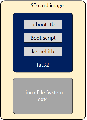
As part of the Yocto GSRD build flow, the SD Card image is built for the SD Card boot flow. This image includes a couple of partitions. One of these partition (a FAT32) includes the U-Boot proper, a Distroboot boot script and the Linux.itb - which includes the Linux kernel image, , the Linux device tree, the 2nd phase fabric design and board configuration (actually several versions of these last 3 components). The 2nd partition (an EXT3 or EXT4 ) includes the Linux file system.
If you want to replace any the components or add a new item in any of these partitions, without having to run again the Yocto build flow.
This can be done through the wic application available on the Poky repository that is included as part of the GSRD build directory: $TOP_FOLDER/gsrd-socfpga/poky/scripts/wic
This command allows you to inspect the content of a SD Card image, delete, add or replace any component inside of the image. This command is also provided with help support:
$ $TOP_FOLDER/gsrd-socfpga/poky/scripts/wic help

Creates a customized OpenEmbedded image.

Usage:  wic [--version]
        wic help [COMMAND or TOPIC]
        wic COMMAND [ARGS]

    usage 1: Returns the current version of Wic
    usage 2: Returns detailed help for a COMMAND or TOPIC
    usage 3: Executes COMMAND

COMMAND:

 list   -   List available canned images and source plugins
 ls     -   List contents of partitioned image or partition
 rm     -   Remove files or directories from the vfat or ext* partitions
 help   -   Show help for a wic COMMAND or TOPIC
 write  -   Write an image to a device
 cp     -   Copy files and directories to the vfat or ext* partitions
 create -   Create a new OpenEmbedded image
 :
 :
-
The wic ls command allows you to inspect or navigate over the directory structure inside of the SD Card image. For example you can observe the partitions in the SD Card image in this way:
# Here you can inspect the content a wic image see the 2 partitions inside of the SD Card image $ $TOP_FOLDER/gsrd-socfpga/poky/scripts/wic ls my_image.wic Num Start End Size Fstype 1 1048576 525336575 524288000 fat32 2 525336576 2098200575 1572864000 ext4 # Here you can naviagate inside of the partition 1 $ $TOP_FOLDER/gsrd-socfpga/poky/scripts/wic ls my_image.wic:1 Volume in drive : is boot Volume Serial Number is 9D2B-6341 Directory for ::/ BOOTSC~1 UIM 2431 2011-04-05 23:00 boot.scr.uimg kernel itb 15160867 2011-04-05 23:00 u-boot itb 1052180 2011-04-05 23:00 3 files 16 215 478 bytes 506 990 592 bytes free -
The wic rm command allows you to delete any of the components in the selected partition. For example, you can delete the kernel.itb image from the partition 1(fat32 partition).
-
The wic cp command allows you to copy any new item or file from your Linux machine to a specific partition and location inside of the SD Card image. For example, you can copy a new kernel.itb to the partition 1.
NOTE: The wic application also allows you to modify any image with compatible vfat and ext* type partitions which also covers images used for eMMC boot flow.
Notices & Disclaimers
Altera® Corporation technologies may require enabled hardware, software or service activation. No product or component can be absolutely secure. Performance varies by use, configuration and other factors. Your costs and results may vary. You may not use or facilitate the use of this document in connection with any infringement or other legal analysis concerning Altera or Intel products described herein. You agree to grant Altera Corporation a non-exclusive, royalty-free license to any patent claim thereafter drafted which includes subject matter disclosed herein. No license (express or implied, by estoppel or otherwise) to any intellectual property rights is granted by this document, with the sole exception that you may publish an unmodified copy. You may create software implementations based on this document and in compliance with the foregoing that are intended to execute on the Altera or Intel product(s) referenced in this document. No rights are granted to create modifications or derivatives of this document. The products described may contain design defects or errors known as errata which may cause the product to deviate from published specifications. Current characterized errata are available on request. Altera disclaims all express and implied warranties, including without limitation, the implied warranties of merchantability, fitness for a particular purpose, and non-infringement, as well as any warranty arising from course of performance, course of dealing, or usage in trade. You are responsible for safety of the overall system, including compliance with applicable safety-related requirements or standards. © Altera Corporation. Altera, the Altera logo, and other Altera marks are trademarks of Altera Corporation. Other names and brands may be claimed as the property of others.
OpenCL* and the OpenCL* logo are trademarks of Apple Inc. used by permission of the Khronos Group™.
Created: August 7, 2024