HPS Zephyr Baseline Example Design
Overview
This user guide demonstrates how to build, package, and execute the Zephyr Real-Time Operating System (RTOS) on an Altera Agilex™ 5 E-Series Hard Processor System (HPS) in the Agilex® 5 FPGA E-Series 065B Premium Development Kit.
The Agilex 5 E-Series architecture pairs high-performance Arm Cortex-A55 and Cortex-A76 cores with rich HPS peripherals. Zephyr provides a modular RTOS footprint suited for real-time determinism applications.
The Arm Trusted Firmware (ATF) acts as the First-Stage Bootloader (FSBL) and Second-Stage Bootloader (SSBL) for Zephyr, as illustrated below:

Zephyr leverage the HPS Baseline System Example Design hardware project. A high-level block diagram fo the HPS Baseline hardware project is shown below:
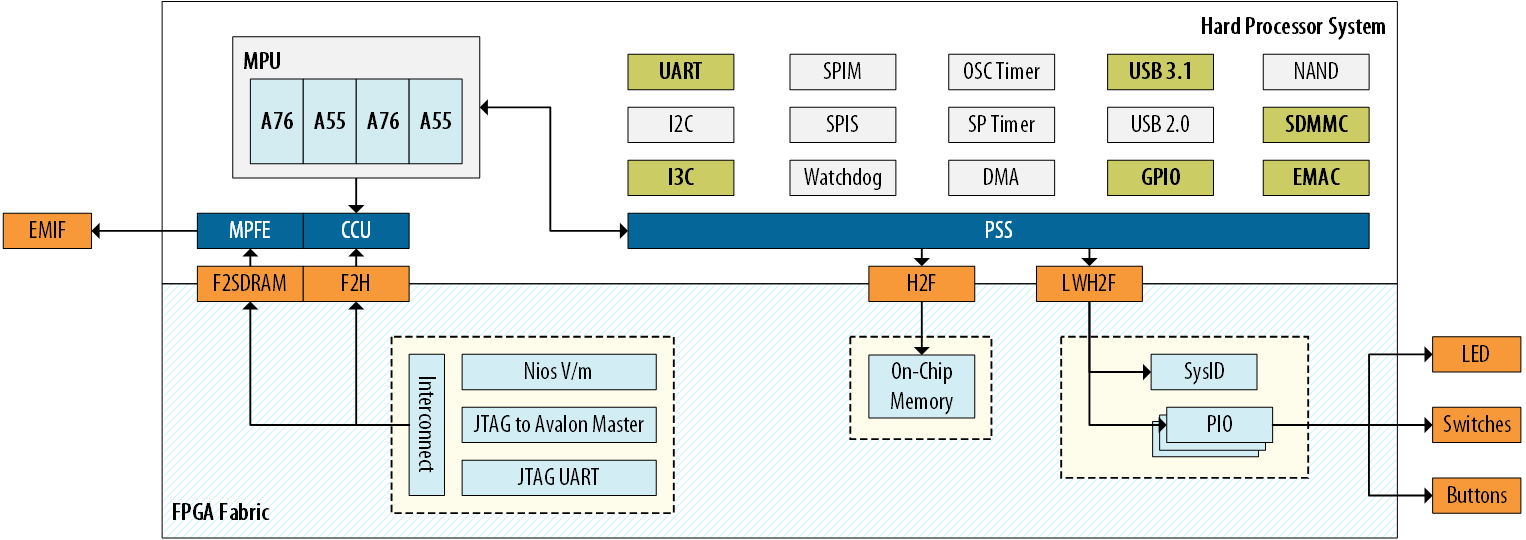
For a complete description of the Quartus hardware project refer to the "GHRD Overview" section of the HPS GSRD User Guide for the Agilex™ 5 FPGA E-Series 065B Modular Development Kit
What you will learn
- Setting up the Zephyr development environment and target the Agilex® 5 FPGA E-Series 065B Premium Development Kit.
- Compiling Zephyr images and boot components for the Agilex® 5 HPS target.
- Booting compiled images from the onboard QSPI memory and a serial console.
Prerequisites
The following items are required to be able to fully exercise this System Example Design:
- Altera® Agilex™ 5 FPGA E-Series 065B Premium Development Kit, ordering code DK-A5E065BB32AEA. Refer to board documentation for more information about the development kit.
- HPS Enablement Expansion Board. Included with the development kit.
- Mini USB Cable. Included with the development kit.
- Micro USB Cable. Included with the development kit.
- Ethernet Cable. Included with the development kit.
- Micro SD card and USB card writer. Included with the development kit.
- Host PC with:
- 64 GB of RAM. Less will be fine for only exercising the binaries, and not rebuilding the System Example Design.
- Linux OS installed. Ubuntu 22.04 LTS was used to create this page, other versions and distributions may work too
- Serial terminal (for example GtkTerm or Minicom on Linux and TeraTerm or PuTTY on Windows)
- Altera® Quartus® Prime Pro Edition Version 26.3
Development Kit Setup
This design targets the Altera® Agilex™ 5 FPGA E-Series 065B Premium Development Kit, ordering code DK-A5E065BB32AEA. Refer to the board documentation for more information.
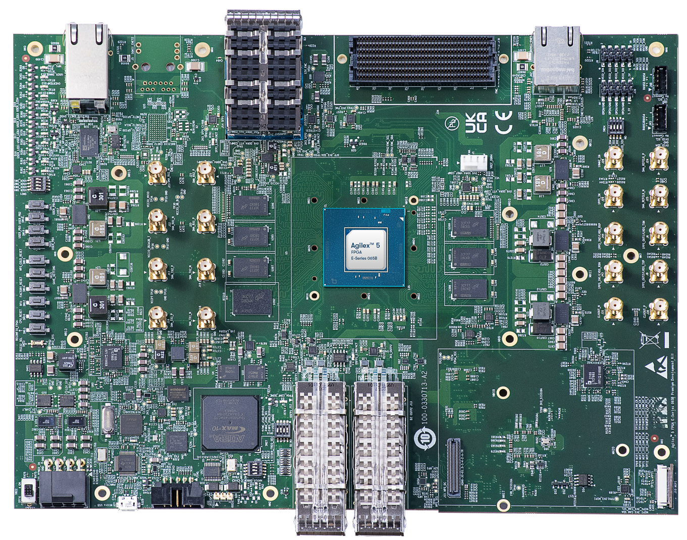
Installing the HPS Enablement Expansion Board
This section shows how to install the included HPS Enablement Daughtercard.
-
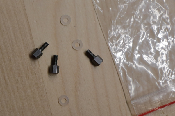
Identify Mounting Hardware: Identify the correct thumb screws and washers needed, they are in a plastic bag:
-
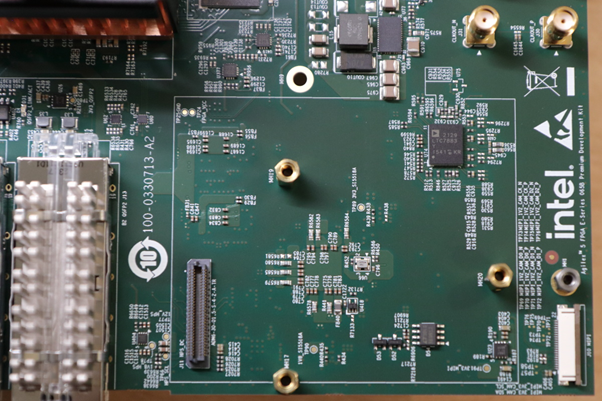
Locate Installation Area: Locate the area on the development board where the HPS Daughtercard needs to be installed:
-
Place Plastic Washers: Place the plastic washers on top of the three hex mounting posts:
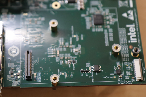
-
Position the HPS Board: Place HPS Board on top of the posts and washers:
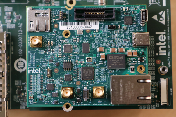
-
Secure the Thumb Screws: Place the hex thumb screws on the two posts, as shown below. Note the 3rd one on the bottom is best unplaced as fully screwing that in may move the board. Also note the thumb screw close to the Ethernet connector is hard to screw, recommend to use small pliers and patience to make it secure. It is important that the HPS Board is secure, and does not move:
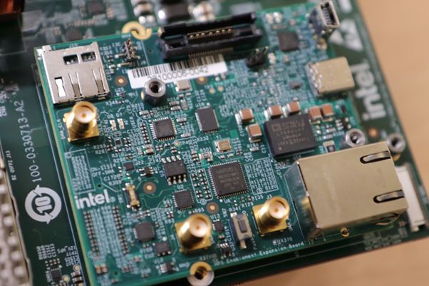
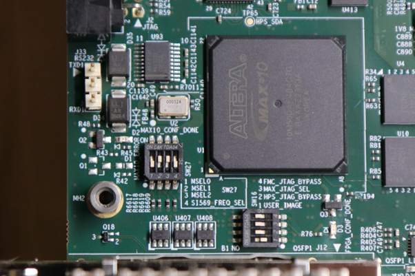
Changing MSEL
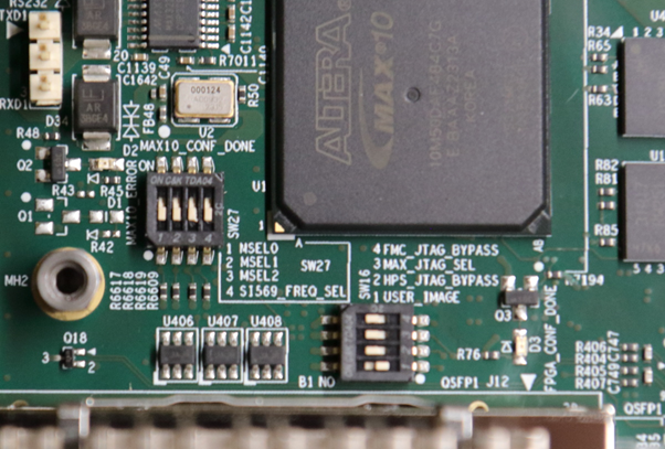
MSEL signals instruct the FPGA device on which configuration scheme to use. Configuration schemes used by the scenarios presented in this guide are JTAG and QSPI. MSEL is changed through dipswitch SW27. Only change the settings while the board is powered off.
Configuration OFF-OFF-OFF-OFF corresponds to JTAG:
Configuration OFF-ON-ON-OFF corresponds to QSPI:
Release Contents
This section outlines the pre-built binary packages, source repositories, and peripheral driver support included with this release.
Pre-built Binaries
Pre-built binaries are available in the following link.
Binaries for a Hello World application and the Shell Subsystem (CLI) are provided in the release package under their respective folders (hello_world and cli). Both folders contain an identical layout described below:
| File Name | Description |
|---|---|
bl31.bin |
Arm Trusted Firmware (TF-A) Stage 3-1 raw binary (EL3 Runtime Firmware / PSCI implementation). |
zephyr.bin |
Final compiled raw binary executable of the Zephyr RTOS application. |
qspi_boot/ |
Directory containing boot images and configuration binaries for QSPI flash memory boot. |
baseline_a55.sof |
Quartus SRAM Object File containing the compiled FPGA fabric configuration bitstream for the Agilex 5 baseline design. |
baseline_a55_hps_auto.sof |
Intermediate SRAM Object File automatically generated by Quartus PFG with the HPS First Stage Bootloader (bl2.hex) integrated into the bitstream. |
bl2.bin |
Arm Trusted Firmware (TF-A) Stage 2 raw binary (First Stage Bootloader / FSBL for the HPS). |
bl2.hex |
Intel HEX representation of bl2.bin generated via objcopy, consumed by Quartus PFG to embed BL2 into the SOF and flash image. |
fip.bin |
Firmware Image Package binary generated by fiptool, packaging the TF-A BL31 runtime firmware and Zephyr OS (bl31.bin + zephyr.bin). |
qspi_flash_image_agilex5_boot.pfg |
Quartus Programming File Generator XML configuration specifying flash partitions, source bitstreams, raw binary payloads, and output targets. |
qspi_image.jic |
JTAG Indirect Configuration file used by the Quartus Prime Programmer to write the complete boot image into target QSPI flash memory via JTAG. |
qspi_image_jic.map |
Memory map text file generated by Quartus PFG detailing flash partition boundaries, start/end byte addresses, and layout. |
qspi_image_jic.rpd |
Raw Programming Data binary containing the full byte-level flash memory image for direct QSPI flash writers or flash emulators. |
Source Repositories
Altera® Quartus® Prime Pro Edition Version 26.3 and the following software component versions integrate the 26.3 release.
| Component | Location | Branch | Commit ID/Tag |
|---|---|---|---|
| Agilex 5 Design | https://github.com/altera-fpga/agilex5e-ed-gsrd | main | QPDS26.3_REL_BASELINE_PR |
| Zephyr RTOS | https://github.com/zephyrproject-rtos/zephyr | main | v4.3.0 |
| Altera Zephyr RTOS | https://github.com/altera-fpga/zephyr-socfpga | socfpga_v4.3.0 | QPDS26.3_REL_BASELINE_PR |
| Arm Trusted Firmware | https://github.com/altera-fpga/arm-trusted-firmware | socfpga_v2.15.0 | QPDS26.3_REL_BASELINE_PR |
Note
The combination of the component versions indicated in the table above has been validated through the use cases described in this page and it is strongly recommended to use these versions together. If you decided to use any component with different version than the indicated, there is not warranty that this will work.
Zephyr Driver Availability
The table below lists the support status for the Hard Processor System (HPS) peripheral drivers included in this Zephyr RTOS release for Agilex 5:
| HPS Peripheral | Supported Status |
|---|---|
| SD Card driver | Yes - CLI App |
| GPIO Driver | Yes |
| I2C Driver | Yes - CLI App |
| UART Driver | Yes |
| Timer Driver | Yes |
| WatchDog Driver | Yes |
| SMP Driver | Yes |
| QSPI Driver | Yes |
| Ethernet Driver | Yes |
| SDM Mailbox Driver | Yes |
| HPS DMA Driver | Yes |
| I3C driver | No |
| EDAC/RAS drivers | No |
| Clock Driver driver | Yes |
| Warm/Cold Reset driver | Yes - CLI App |
Note
Drivers with support status 'No' have not completed their validation in hardware.
Drivers with support status Yes - \<Application\> have been validation in hardware under the specified application only.
Testing Pre-Compiled Binaries
This section describes how to test the pre-built Zephyr images and Arm Trusted Firmware binaries in the Agilex® 5 FPGA E-Series 065B Premium Development Kit. Use this flow to confirm the board configuration, OS bring-up and verify console output without building the target software stack from source.
Development Kit Configuration
Complete the following physical connections and switch checks before powering on the board:
- Leave all jumpers and switches in their default configuration.
- Install the HPS Enablement Expansion Board
- Connect mini USB cable from vertical connector on HPS Daughtercard to host PC. This is used for the HPS serial console.
- Connect micro USB cable from development board to host PC. This is used by the tools for JTAG communication.
Serial Console Setup
Configure the host serial terminal application to communicate with the HPS UART interface before booting the target:
The HPS Enablement Daughtercard has a built-in FTDI USB to Serial converter chip that allows the host computer to see the board as a virtual serial port. Ubuntu and other modern Linux distributions have built-in drivers for the FTDI USB to Serial converter chip, so no driver installation is necessary on those platforms. Microsoft Windows 10 and 11 automatically install the necessary drivers.
The serial communication parameters are:
- Baud-rate: 115,200
- Parity: none
- Flow control: none
- Stop bits: 1
On Windows, utilities such as TeraTerm and PuTTY can be used to connect to the board. They are easily configured from the tool menus.
On Linux, the minicom utility can be used. Here is how to configure it:
The virtual serial port is usually named /dev/ttyUSB0. In order to determine the device name associated with the virtual serial port on your host PC, please perform the following:
- Use the following command to determine which USB serial devices are already installed:
ls /dev/ttyUSB* - Connect mini USB cable from J7 to the PC. This will enable the PC to communicate with the board, even if the board is not powered yet.
- Use the
ls /dev/ttyUSB*command command again to determine which new USB serial device appeared. - Install minicom application on host PC, if not installed:
- On Ubuntu, use
sudo apt-get install minicom
- On Ubuntu, use
- Configure minicom with the next command:
Under Serial Port Setup choose the following:
- Serial Device: /dev/ttyUSB0 (edit to match the system as necessary)
- Bps/Par/Bits: 115200 8N1
- Hardware Flow Control: No
- Software Flow Control: No
- Hit [ESC] to return to the main configuration menu
Select Save Setup as dfl to save the default setup. Then select Exit.
Test Zephyr Pre-compiled Images
Precompiled test applications for Zephyr OS include Hello World and a command-line interface (CLI).
Run the command for the application you want to test:
Step 1: Download Prebuild Binaries - Download the Hello World QSPI image for testing.
mkdir agilex5_zbaseline
cd agilex5_zbaseline
export CWD=$(pwd)
cd $CWD
mkdir qspi_bin_prebuilt-hello
cd qspi_bin_prebuilt-hello
wget https://releases.rocketboards.org/2026.10/zephyr/agilex5_dk_a5e065bb32aea_zephyr/hello_world/qspi_boot/qspi_image.jic
Step 2: Flash the Pre-built Binary to Onboard QSPI Memory - Prepare the board for JTAG programming and write the JIC image into QSPI flash.
- Power down the board.
- Set MSEL dipswitch (
SW27) to JTAG:OFF-OFF-OFF-OFF. - Power up the board.
- Write JIC image to the QSPI memory.
Run the following commands to program the flash memory:
jtagconfig --setparam 1 JtagClock 16M
quartus_pgm -c 1 -m jtag -o "pvi;$CWD/qspi_bin_prebuilt-hello/qspi_image.jic"
Step 3: Boot Zephyr OS - Switch the configuration mode to QSPI and verify the serial console output.
- Power down the board.
- Set MSEL dipswitch (
SW27) to ASX4 (QSPI):OFF-ON-ON-OFF. - Power up the board.
- Wait for the Zephyr to boot.
- Verify the boot log matches the expected output below.
NOTICE:  DDR: Reset type is 'Power-On'
NOTICE:  IOSSM: Calibration success status check...
NOTICE:  IOSSM: All EMIF instances within the IO96 have calibrated successfully!
NOTICE:  DDR: Calibration success
NOTICE:  DDR: ECC is enabled
NOTICE:  IOSSM: Memory initialized successfully on IO96B
NOTICE:  ###DDR:init success###
NOTICE:  DFI interface selected successfully to SDEMMC
NOTICE:  SOCFPGA: QSPI boot
NOTICE:  BL2: v2.15.1(release):09c4dc6
NOTICE:  BL2: Built : 19:06:44, Oct 27 2026
NOTICE:  BL2: Booting BL31
NOTICE:  SOCFPGA: Boot Core = 0
NOTICE:  SOCFPGA: CPU ID = 0
NOTICE:  SOCFPGA: Setting CLUSTERECTRL_EL1
NOTICE:  BL31: v2.15.1(release):09c4dc6
NOTICE:  BL31: Built : 19:06:44, Oct 27 2026
*** Booting Zephyr OS build v4.3.0-30-g91f336578525 ***
Secondary CPU core 1 (MPID:0x100) is up
Secondary CPU core 2 (MPID:0x200) is up
Secondary CPU core 3 (MPID:0x300) is up
Hello World! intel_socfpga_agilex5_socdk/agilex5
Step 1: Download Prebuild Binaries - Download the CLI QSPI image for testing.
mkdir agilex5_zbaseline
cd agilex5_zbaseline
export CWD=$(pwd)
cd $CWD
mkdir qspi_bin_prebuilt-cli
cd qspi_bin_prebuilt-cli
wget https://releases.rocketboards.org/2026.10/zephyr/agilex5_dk_a5e065bb32aea_zephyr/cli/qspi_boot/qspi_image.jic
Step 2: Flash the Pre-built Binary to Onboard QSPI Memory - Prepare the board for JTAG programming and write the JIC image into QSPI flash.
- Power down the board.
- Set MSEL dipswitch (
SW27) to JTAG:OFF-OFF-OFF-OFF. - Power up the board.
- Write JIC image to the QSPI memory.
Run the following commands to program the flash memory:
jtagconfig --setparam 1 JtagClock 16M
quartus_pgm -c 1 -m jtag -o "pvi;$CWD/qspi_bin_prebuilt-cli/qspi_image.jic"
Step 3: Boot Zephyr OS - Switch the configuration mode to QSPI and verify the serial console output.
- Power down the board.
- Set MSEL dipswitch (
SW27) to ASX4 (QSPI):`OFF-ON-ON-OFF. - Power up the board.
- Wait for the Zephyr to boot.
- Verify the boot log matches the expected output below.
NOTICE:  DDR: Reset type is 'Power-On'
NOTICE:  IOSSM: Calibration success status check...
NOTICE:  IOSSM: All EMIF instances within the IO96 have calibrated successfully!
NOTICE:  DDR: Calibration success
NOTICE:  DDR: ECC is enabled
NOTICE:  IOSSM: Memory initialized successfully on IO96B
NOTICE:  ###DDR:init success###
NOTICE:  DFI interface selected successfully to SDEMMC
NOTICE:  SOCFPGA: QSPI boot
NOTICE:  BL2: v2.15.1(release):09c4dc6
NOTICE:  BL2: Built : 19:06:44, Oct 27 2026
NOTICE:  BL2: Booting BL31
NOTICE:  SOCFPGA: Boot Core = 0
NOTICE:  SOCFPGA: CPU ID = 0
NOTICE:  SOCFPGA: Setting CLUSTERECTRL_EL1
NOTICE:  BL31: v2.15.1(release):09c4dc6
NOTICE:  BL31: Built : 19:06:44, Oct 27 2026
*** Booting Zephyr OS build v4.3.0-30-g91f336578525 ***
Secondary CPU core 1 (MPID:0x100) is up
Secondary CPU core 2 (MPID:0x200) is up
Secondary CPU core 3 (MPID:0x300) is up
intel_socfpga_agilex5_socdk: Starting Command Line Interface...
agilex5$
Compiling from Source and Testing
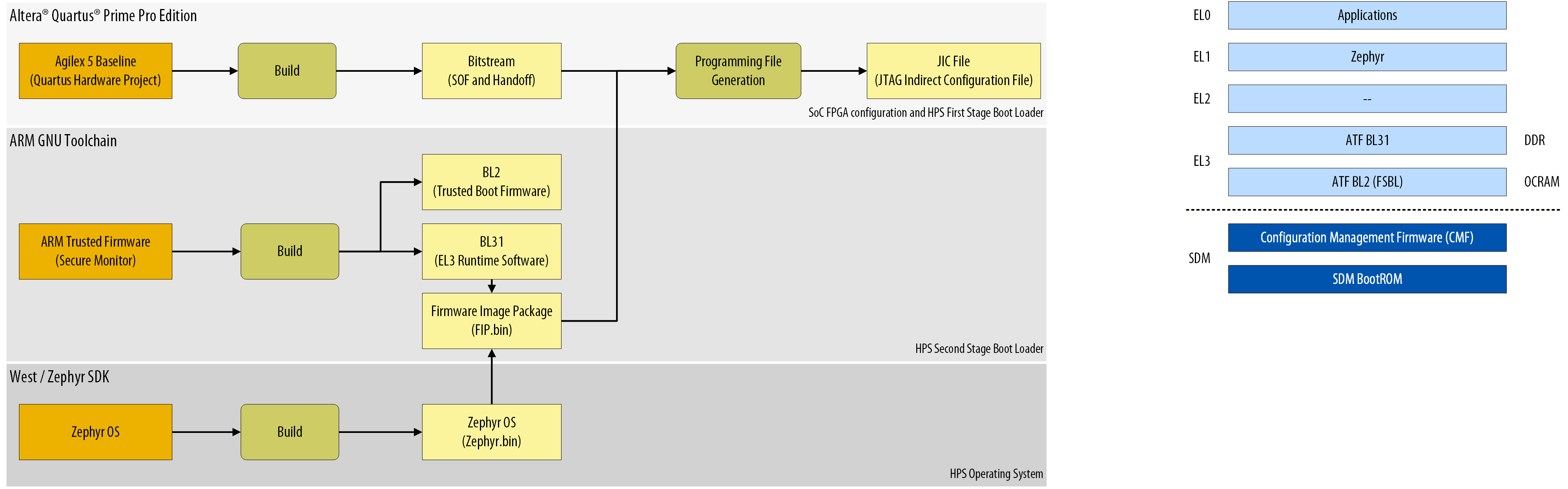
Follow the steps in this section to set up the toolchain, compile Zephyr and Arm Trusted Firmware (ATF) from source, and package an RTOS application into a bootable QSPI flash image using the Quartus Programming File Generator.
The build process is shown in the image below.
Environment Setup for Source Compilation
Prepare the Linux host environment, Quartus tools, cross-compilation toolchain, FPGA hardware bitstream, and Zephyr SDK before compiling the software stack.
-
Install System Dependencies: Execute the command below.
sudo apt-get install --no-install-recommends \ git cmake ninja-build gperf ccache dfu-util device-tree-compiler wget \ python3-dev python3-pip python3-setuptools python3-tk python3-wheel \ python3-venv xz-utils file libpython3-dev make gcc gcc-multilib \ g++-multilib libsdl2-dev libmagic1 libguestfs-tools libssl-dev -
Setup the Quartus Toolchain: The command below assume that Altera® Quartus® Prime Pro Edition Version 26.3 is installed in your home directory. Adjust the path if necessary.
-
Establish Workspace Staging Area: Create the top-level working directory and export the
CWDenvironment variable. -
Download and Register the Arm GNU Toolchain: Configure the Arm64 cross-compiler environment required to build Arm Trusted Firmware.
cd $CWD wget https://developer.arm.com/-/media/Files/downloads/gnu/14.3.rel1/binrel/\ arm-gnu-toolchain-14.3.rel1-x86_64-aarch64-none-linux-gnu.tar.xz tar xf arm-gnu-toolchain-14.3.rel1-x86_64-aarch64-none-linux-gnu.tar.xz rm -f arm-gnu-toolchain-14.3.rel1-x86_64-aarch64-none-linux-gnu.tar.xz export PATH=`pwd`/arm-gnu-toolchain-14.3.rel1-x86_64-aarch64-none-linux-gnu/bin/:$PATH export ARCH=arm64 export CROSS_COMPILE=aarch64-none-linux-gnu- -
Compile the Agilex 5 Baseline FPGA Bitstream: Set up the workspace for the Quartus hardware project compilation:
cd $CWD
rm -rf agilex5_065b_base.qspi
mkdir agilex5_065b_base.qspi
cd agilex5_065b_base.qspi
export HW_CWD=`pwd`
Download and build the Quartus hardware design.
cd $HW_CWD
rm -rf agilex5_soc_devkit_ghrd && mkdir agilex5_soc_devkit_ghrd && cd agilex5_soc_devkit_ghrd
wget https://github.com/altera-fpga/agilex5-ed-hps-baseline/releases/download/QPDS26.3_REL_BASELINE_PR/dk-a5e065bb32aea-enablement-baseline-a55.zip
unzip dk-a5e065bb32aea-enablement-baseline-a55.zip
rm -f dk-a5e065bb32aea-enablement-baseline-a55.zip
make baseline_a55-build
Once the build completes, the generated SRAM Object File (
.sof) will be located at$HW_CWD/agilex5_soc_devkit_ghrd/output_files/baseline_a55.sof -
Install and Initialize the Zephyr SDK: Download, verify, and unpack the Zephyr SDK:
cd $CWD
wget https://github.com/zephyrproject-rtos/sdk-ng/releases/download/v0.17.4/zephyr-sdk-0.17.4_linux-x86_64.tar.xz
wget -O - https://github.com/zephyrproject-rtos/sdk-ng/releases/download/v0.17.4/sha256.sum | shasum --check --ignore-missing
tar xvf zephyr-sdk-0.17.4_linux-x86_64.tar.xz
rm -rf zephyr-sdk-0.17.4_linux-x86_64.tar.xz
cd zephyr-sdk-0.17.4
# Run the SDK setup script to configure toolchains, host tools, and CMake integration
./setup.sh -t all
Register the toolchain environment variables in your active shell:
Compile Arm Trusted Firmware (ATF)
Build the Arm Trusted Firmware First-Stage Bootloader (bl2), EL3 runtime firmware (bl31), and Firmware Image Package utility (fiptool) configured for QSPI boot.
-
Clone and Compile the ATF Source Tree: Clone the Altera Arm Trusted Firmware repository and build the
bl2andbl31targets for the Agilex 5 platform. -
Compile the ATF Firmware Image Package Utility (
fiptool): Build thefiptoolhost executable and copy it to the top-level working directory.The compilation produces the following output build artifacts:
$CWD/arm-trusted-firmware-qspi/build/agilex5/release/bl2.bin$CWD/arm-trusted-firmware-qspi/build/agilex5/release/bl31.bin$CWD/fiptool
Compile Zephyr Kernel and Applications
Zephyr build trees are managed using the west meta-tool. In this flow, the upstream Zephyr repository is initialized, dependencies are fetched, and the core tree is substituted with the Altera downstream branch supporting Agilex 5 HPS peripherals.
The Altera downstream Zephyr repository provides sample applications to validate Hard Processor System (HPS) peripherals, as detailed in the following table.
| Component / Feature | Application Path | Description |
|---|---|---|
| HelloWorld | samples/hello_world/ |
Basic sanity test that prints "Hello World!" and board target information to verify toolchain, boot flow, and serial console output. |
| GPIO | samples/basic/blinky/ |
Demonstrates the GPIO driver API by toggling an LED (led0 devicetree alias) on and off at 1-second intervals and printing the status. |
| Timer/Counter | samples/drivers/counter/alarm/ |
Demonstrates the counter driver API by starting a hardware timer, setting an alarm callback, and updating the alarm interval upon interrupt. |
| Watchdog | samples/drivers/watchdog/ |
Configures the watchdog timer to reset the SoC upon expiration, feeds the watchdog 5 times, and then allows it to expire to test reset behavior. |
| UART | samples/drivers/uart/echo_bot |
Implements an interrupt-driven UART echo bot that buffers incoming characters in a message queue and echoes completed lines back to the console. |
| QSPI | samples/drivers/soc_flash_qspi |
Validates the QSPI NOR flash driver by retrieving geometry, erasing flash blocks, writing test data, and verifying the readback and erase data integrity. |
| SDM Mailbox | samples/subsys/sip_svc/ |
Uses the SiP SVC subsystem to communicate with the Secure Device Manager (SDM) via ARM EL3 SMC calls, sending mailbox commands to query chip voltage. |
| HPS DMA | samples/drivers/dma/mem_to_mem/ |
Demonstrates asynchronous memory-to-memory transfers using the Synopsys DesignWare AXI DMA controller with linked-list descriptors and cache maintenance. |
| CLI | subsys/shell/ |
Implements Zephyr's interactive command-line shell, reading input and executing registered commands. |
The build procedure in this section demonstrates targeting the HPS General-Purpose I/O (GPIO) block using the blinky application.
-
Initialize Python Virtual Environment and Checkout Repositories: Create a Python virtual environment, install
west, and initialize the upstream Zephyr workspace.cd $CWD python3 -m venv ~/.zephyrproject/.venv source ~/.zephyrproject/.venv/bin/activate pip3 install wheel west west init -m https://github.com/zephyrproject-rtos/zephyr --mr v4.3.0 zephyrproject cd $CWD/zephyrproject west update west zephyr-export pip install -r $CWD/zephyrproject/zephyr/scripts/requirements.txt -
Switch to the Altera Downstream Zephyr Repository: Replace the default
zephyrdirectory with the Alterasocfpga_v4.3.0branch and update workspace modules. -
Build the Zephyr GPIO Application Image: Compile the
blinkysample application targeting the Agilex 5 SoC Development Kit.cd $CWD/zephyrproject/zephyr west build -b intel_socfpga_agilex5_socdk samples/basic/blinky -d agilex5Once the build completes, the generated target executable is located at
$CWD/zephyrproject/zephyr/agilex5/zephyr/zephyr.bin.
Create the Zephyr Boot Artifacts
This example design boots from the QSPI flash. To construct the boot image, fiptool packages the Secure Monitor (bl31.bin) and non-secure OS (zephyr.bin) into a single Firmware Image Package (fip.bin). The Quartus Programming File Generator then maps bl2.hex into initial boot sectors and places fip.bin at offset 0x03C00000.
-
Stage ATF and Zephyr Payloads into a Unified FIP Container: Create the
qspi_binpackaging directory, copybl2.bin, and generatefip.bincombiningbl31.binandzephyr.bin. -
Create the Quartus Programming File Generator Specification (
qspi_flash_image_agilex5_boot.pfg): Write the XML configuration file defining the QSPI flash layout and partition assignments.cd $CWD/qspi_bin base64 -d <<'EOF' | gunzip > "qspi_flash_image_agilex5_boot.pfg" H4sICERJ62oCA3FzcGlfZmxhc2hfaW1hZ2VfYWdpbGV4NV9ib290LnBmZwCtU9uO2yAQfc9XID4g drLrPtmWcnO1ldqkyVbqGyJh7CD5ViDZpF9fsONg3NVuVypPMDDnHObMhHWaoTMIyasywhMcjxAK JSjFy0yiw0mqqiBsTxgXER57GBUVgwjPdj8fsdc8rk6qPimS8hykCZjVD6KSFjrjl6w54QXNACMN BgdViauGxEhda33/5WmBu/QGwuSSqlZamPScGwmHqmRUXFv8Nv/rbIP/purnvYPqubDvM+5WC7Ld LD/KivZcyRdam2r/u4I0p/JIGJz5AQhncdKcl+15EnrD+84Ir+dEY5c39Cs0epQAWlj77iHEWYTn 3YlMXItqqo7oWEtiNhHe59PxES443lMJOS+B0CAYyyoNPfPAarrDt4pcAaGgL4Nu6iL90t1M2M4T 3Ijc6jeJKbPWmPJ6vOdl6HWJLY8D7FTUUvWjXWc9T4PvP/zp55bIrfywIEJx4zISIEGcgTVSU34B RiShjIkm0G39i39bGEEvNknM6hLBJjZ2rNfP5OlbstY4/LcW6A/66DUV/lCFb1XQk6osf3tymf2W eTP5X5T6kw+LwcffINaGvsLsdv3AwryiDEQ8C1ZL/1Mwnz9MZ6vHXZdyux0NQdrWoFLyrCygVLYx bAzVesYbafdfk1t1nJrc29rMY2+Geg3vTKpl+ACpqYzD2jW5gbYzYZv/Dcr+WX9cT22axaM/aEP3 CiIGAAA= EOF -
Convert
bl2.binto HEX Format: Useobjcopyto convert the rawbl2.binbinary into an Intel HEX image (bl2.hex). -
Generate the QSPI RPD Boot Image: Link the compiled FPGA
.sofbitstream and runquartus_pfgto generate the final QSPI flash programming files.cd $CWD/qspi_bin ln -sf $HW_CWD/agilex5_soc_devkit_ghrd/output_files/baseline_a55.sof baseline_a55.sof quartus_pfg -c qspi_flash_image_agilex5_boot.pfg deactivateThis command generates the final programming image at
$CWD/qspi_bin/qspi_image.jicalong withqspi_image.rpdandqspi_image.map.
Compilation Artifacts Summary
Once the build completes, the $CWD/qspi_bin/ directory contains the following files:
| File | Description |
|---|---|
bl2.bin |
ATF FSBL raw binary executed first by Simics. |
bl2.hex |
ATF FSBL translated to Intel HEX format for PFG packaging. |
bl31.bin |
ATF BL31 EL3 runtime monitor binary. |
zephyr.bin |
Compiled Zephyr kernel and application binary. |
fip.bin |
Combined Firmware Image Package containing BL31 and Zephyr. |
qspi_image.jic |
QSPI flash memory raw programming data image for Development Kit. |
Testing the GPIO Application
Program the generated QSPI image onto the development kit and verify that the GPIO blinky application executes as expected.
-
Flash the Compiled Binary to Onboard QSPI Memory: Configure the board for JTAG mode and write the generated
qspi_image.jicfile to QSPI flash.- Power down the board.
- Set MSEL dipswitch
SW27to JTAG:OFF-OFF-OFF-OFF. - Power up the board.
- Write JIC image to the QSPI memory.
Execute the following commands to program the QSPI flash:
-
Boot Zephyr OS: Switch the board to QSPI configuration mode and observe the LED and serial console output.
- Power down the board.
- Set MSEL dipswitch
SW27to ASX4 (QSPI):OFF-ON-ON-OFF. - Power up the board.
- Wait for the Zephyr to boot.
Upon succesful execution HPS LED starts blinking. Refer to the transcript below for a serial session output after succesful execution.
NOTICE:  DDR: Reset type is 'Power-On'
NOTICE:  IOSSM: Calibration success status check...
NOTICE:  IOSSM: All EMIF instances within the IO96 have calibrated successfully!
NOTICE:  DDR: Calibration success
NOTICE:  DDR: ECC is enabled
NOTICE:  IOSSM: Memory initialized successfully on IO96B
NOTICE:  ###DDR:init success###
NOTICE:  DFI interface selected successfully to SDEMMC
NOTICE:  SOCFPGA: QSPI boot
NOTICE:  BL2: v2.15.1(release):QPDS26.3_REL_BASELINE_PR
NOTICE:  BL2: Built : 09:51:25, Nov  4 2026
NOTICE:  BL2: Booting BL31
NOTICE:  SOCFPGA: Boot Core = 0
NOTICE:  SOCFPGA: CPU ID = 0
NOTICE:  SOCFPGA: Setting CLUSTERECTRL_EL1
NOTICE:  BL31: v2.15.1(release):QPDS26.3_REL_BASELINE_PR
NOTICE:  BL31: Built : 09:51:25, Nov  4 2026
*** Booting Zephyr OS build QPDS26.3_REL_BASELINE_PR ***
Secondary CPU core 1 (MPID:0x100) is up
Secondary CPU core 2 (MPID:0x200) is up
Secondary CPU core 3 (MPID:0x300) is up
LED state: OFF
LED state: ON
LED state: OFF
LED state: ON
Troubleshooting
This section provides reference solutions for common environment and build configuration errors encountered when setting up or recompiling the Zephyr software stack.
Sphinx Dependency Conflict During Environment Setup
Installing Sphinx packages on non-standard host Python environments can trigger version incompatibility conflicts with docutils:
ERROR: sphinx-tabs 3.4.1 has requirement docutils~=0.18.0, but you'll have docutils 0.19 which is incompatible.
ERROR: sphinx-rtd-theme 1.2.2 has requirement docutils<0.19, but you'll have docutils 0.19 which is incompatible
Resolve the dependency pin by reinstalling the core documentation packages within the active Python environment:
Stale Build Artifacts When Recompiling Applications
Rebuilding alternate Zephyr applications inside an existing build directory causes configuration mismatch errors:
ERROR: Build directory ".../zephyr/agilex5" is for application ".../hello_world", but source directory ".../blinky" was specified; please clean it, use --pristine, or use --build-dir to set another build directory
Force a clean build using the -p always flag:
Documentation & Upstream Resources
Notices & Disclaimers
Altera® Corporation technologies may require enabled hardware, software or service activation. No product or component can be absolutely secure. Performance varies by use, configuration and other factors. Your costs and results may vary. You may not use or facilitate the use of this document in connection with any infringement or other legal analysis concerning Altera or Intel products described herein. You agree to grant Altera Corporation a non-exclusive, royalty-free license to any patent claim thereafter drafted which includes subject matter disclosed herein. No license (express or implied, by estoppel or otherwise) to any intellectual property rights is granted by this document, with the sole exception that you may publish an unmodified copy. You may create software implementations based on this document and in compliance with the foregoing that are intended to execute on the Altera or Intel product(s) referenced in this document. No rights are granted to create modifications or derivatives of this document. The products described may contain design defects or errors known as errata which may cause the product to deviate from published specifications. Current characterized errata are available on request. Altera disclaims all express and implied warranties, including without limitation, the implied warranties of merchantability, fitness for a particular purpose, and non-infringement, as well as any warranty arising from course of performance, course of dealing, or usage in trade. You are responsible for safety of the overall system, including compliance with applicable safety-related requirements or standards. © Altera Corporation. Altera, the Altera logo, and other Altera marks are trademarks of Altera Corporation. Other names and brands may be claimed as the property of others.
OpenCL* and the OpenCL* logo are trademarks of Apple Inc. used by permission of the Khronos Group™.