Robotics Camera System Example Design for Agilex™ 5 Devices
Overview
This example design demonstrates a compact, robotics-oriented glass-to-glass camera path on the Agilex™ 5 FPGA E-Series 065B Modular Development Kit. Sensor capture, real-time conditioning, and display run largely in programmable logic, while the Hard Processor System (HPS) hosts Linux for application software:
- MIPI CSI-2 sensor interface: connects a Framos FSM:GO IMX678C Camera Modules to the FPGA using industry-standard MIPI D-PHY and CSI-2, bringing raw Bayer frames from the imager into the fabric for low-latency processing.
- ISP Lite pipeline: a streamlined Image Signal Processor in FPGA logic converts raw sensor data into display-ready video (demosaic, color correction, and related conditioning) using IP from the VVP IP Suite, without the full multi-stage HDR pipeline of the larger camera solution designs.
- DisplayPort output: streams the processed video to a local monitor through the kit’s DisplayPort interface so you can verify exposure, framing, and pipeline behavior during bring-up and demonstration.
- HPS and Linux software stack: runs on the ARM cores in the HPS with drivers and services to configure the video path; the platform is intended as a foundation for higher-level robotics stacks (for example perception nodes, recording, or ROS 2 integration) rather than as a standalone camera product.
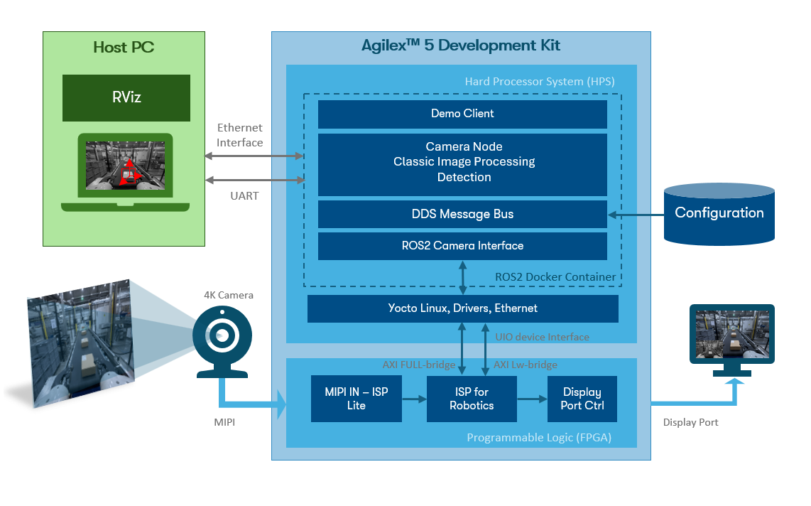
High-Level Block Diagram of the Robotics Camera System Example Design.
The figure shows the end-to-end glass-to-glass path and the main Platform Designer subsystems. The MIPI In subsystem connects the FRAMOS IMX678 on the kit MIPI connector through MIPI D-PHY and MIPI CSI-2 receive IP (with format conversion) to produce a 12-bit Bayer stream in the fabric. The ISP In subsystem uses a Switch (Bayer) to select live sensor data or a Test Pattern Generator path (via Remosaic) for pipeline debug without a camera attached. The ISP Lite subsystem then performs first-stage conditioning—Black Level Correction, White Balance, Demosaic, and Color Correction Matrix—to convert Bayer data into an RGB stream.
Between ISP Lite and the display, the ISP Robotics subsystem provides robotics-oriented processing. Clipper and Scaler blocks resize the stream (for example from 3840×2160 to 1920×1080 and 960×540 branches). Color Space Converter and Color Plane Merger blocks derive 8-bit and 10-bit grayscale streams for vision workloads. Frame Writer, Frame Reader, and Frame Buffer paths connect to EMIF subsystems (DDR4 banks 2B and 3B) so the HPS can access processed frames through MSGDMA. The ISP Lite Out subsystem buffers the main 4K RGB path; its Mixer composites the full-resolution stream with the scaled grayscale preview, an optional Altera icon overlay, and test patterns, and DP Tx & PHY drives DisplayPort 1.4 for local monitoring.
A Nios® V/m subsystem acts as the soft processor for video pipeline control, programming IP CSRs in the MIPI In, ISP In, ISP Lite, and ISP Lite Out subsystems. The HPS subsystem is the Agilex™ 5 HPS with dedicated DDR4 EMIF, UART, Ethernet, I2C, and SD interfaces; Linux configures the ISP Robotics subsystem CSRs and moves frame data over HPS-to-FPGA and/or F2SDRAM bridges for higher-level robotics software (for example ROS 2 perception nodes).
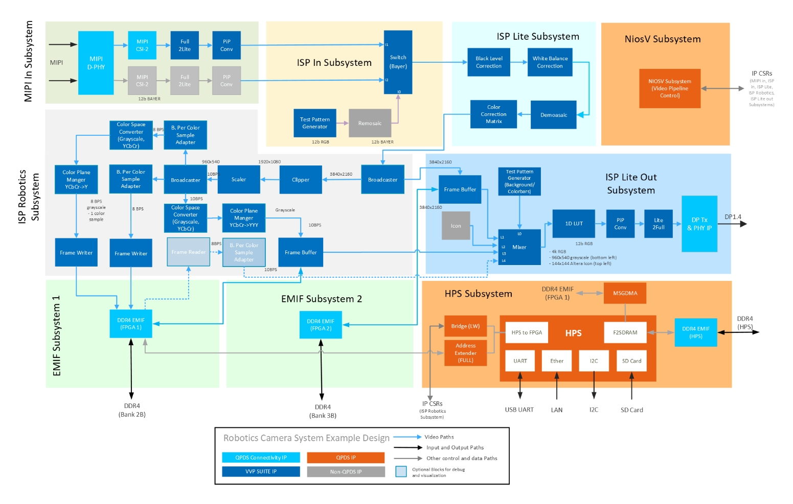
High-Level Hardware Block Diagram of the Robotics Camera System Example Design.
Blue interconnect in the diagram is the live video path (MIPI In → ISP In → ISP Lite → ISP Robotics → ISP Lite Out → DisplayPort). Dashed paths are control and memory access from the Nios® V and HPS subsystems.
Subsystem names and grouping match the Modular Design Toolkit (MDT) view and the variant XML (AGX_5E_Modular_Devkit_HPS_ISP_CAM_ROB.xml).
The hardware variant AGX_5E_Modular_Devkit_HPS_ISP_CAM_ROB.xml is built with the Modular Design Toolkit from the https://github.com/altera-fpga/agilex-ed-robotics repository. See the HPS_ISP_CAM_ROBOTICS README for MDT create and build steps.
Pre-requisites
The following are required to be able to fully exercise the Agilex™ 5 Modular Development Kit:
Software Requirements to run
- Host PC with
- 4 GB of RAM
- Linux OS installed
- Serial terminal (for example GtkTerm or Minicom on Linux and TeraTerm or PuTTY on Windows)
- Tool to write SD card images (USBImager or similar)
- Altera® Quartus® Prime Pro Edition Version 26.1 Programmer and Tools
- Docker
- Rocker (recommended to run graphical applications in a container on a host PC)
Software Requirements to build
- 8 GB of RAM
- Linux OS installed
- ~62 GB free storage (~2 GB Quartus® build, ~60 GB Yocto/KAS)
- Python/PIP/KAS for Yocto (or a suitable container)
- Altera® Quartus® Prime Pro Edition Version 26.1 with Agilex™ 5 device support
- FPGA NiosV/g Open-Source Tools 26.1 (installed with Quartus® Prime)
Hardware Requirements
- Agilex™ 5 FPGA E-Series 065B Modular Development Kit (ordering code MK-A5E065BB32AEA)
- Power supply
- 1 × Micro USB cable (JTAG and HPS serial console)
- 2 × Ethernet cables (one for the board, one for the host PC). An Ethernet router or switch may be needed for a local network
- Micro SD card and USB card writer (minimum 8 GB)
- DisplayPort cable, or HDMI cable with DP to HDMI Adapter (4Kp30 capable recommended when using DisplayPort output)
- 4Kp30 capable monitor or Video Capture Card (like DIGITNOW USB Video Capture Card)
For designs that use the FRAMOS sensor (see the design-specific user guide):
- 1 Framos FSM:GO IMX678C Camera Modules, with:
- (Optional) Framos Tripod Mount Adapter and Tripod
- 150mm flex-cable or 300mm micro-coax cable per camera module
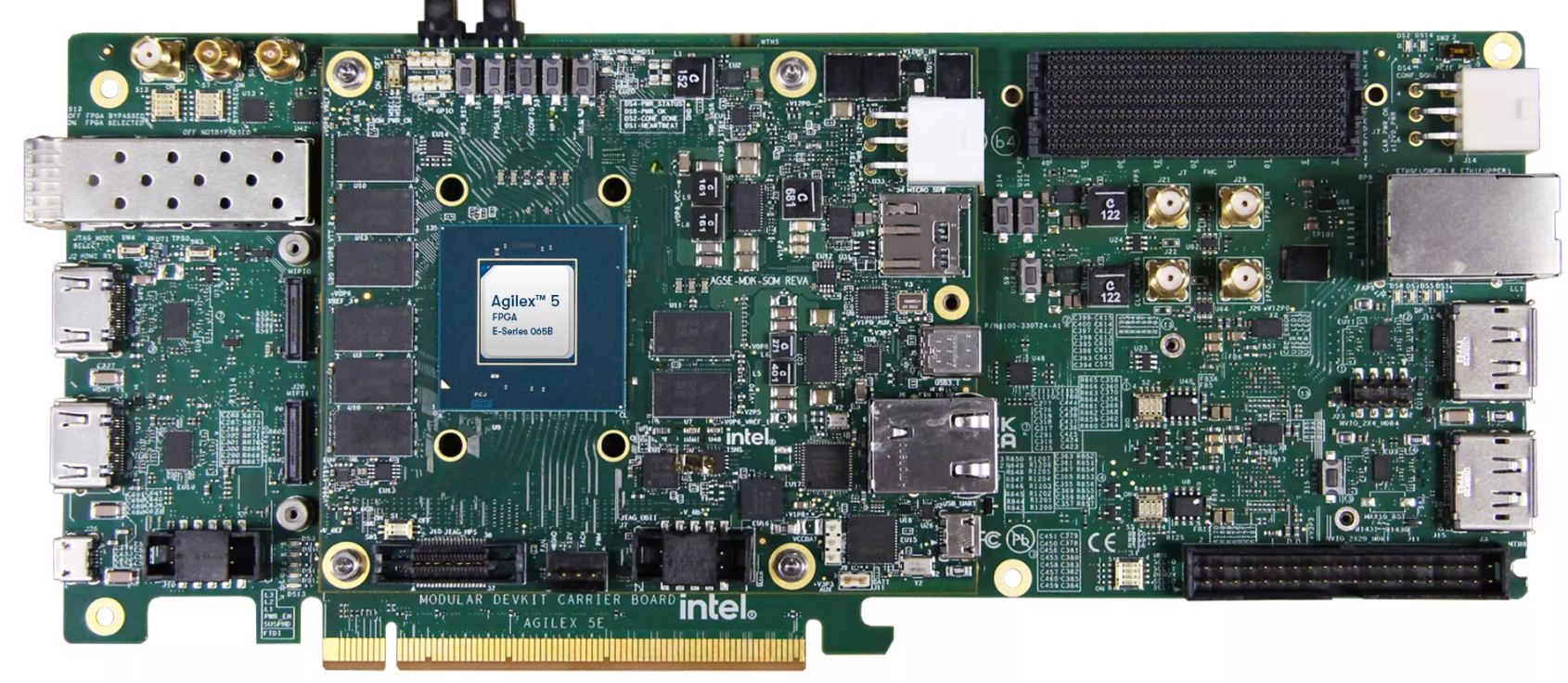
Agilex™ 5 FPGA E-Series 065B Modular Development Kit.
Sources
The sources below are recommended for Quartus® 26.1 builds. This is an example design and is not intended for production deployment.
Example Design Source Repositories.
| Component | Location | Branch |
|---|---|---|
| Assets Release Tag | https://github.com/altera-fpga/agilex-ed-robotics/releases/tag/rel-camera-26.1 | rel-camera-26.1 |
| Altera Robotics | https://github.com/altera-fpga/agilex-ed-robotics | rel/26.1 |
| Modular Design Toolkit | https://github.com/altera-fpga/modular-design-toolkit | rel/26.1 |
| Altera ROS2 | https://github.com/altera-fpga/altera-ros2 | main |
| Linux (Yocto/KAS) | https://github.com/altera-fpga/agilex-ed-robotics/tree/rel/26.1/sw | rel/26.1 |
| Linux kernel | https://github.com/altera-fpga/linux-socfpga | socfpga-6.18.2-lts |
| Arm Trusted Firmware | https://github.com/altera-fpga/arm-trusted-firmware | socfpga_v2.14.0 |
| U-Boot | https://github.com/altera-fpga/u-boot-socfpga | socfpga_v2026.01 |
| Yocto Project: poky | https://git.yoctoproject.org/poky | wrynose |
Getting Started — run with pre-built binaries
Follow these steps to run the example on the Agilex™ 5 E-Series 065B Modular Development Kit.
Download the minimum pre-built binaries
| Boot Source | Link |
|---|---|
| SD Card Image | wic.gz, wic.bmap |
| QSPI | top.hps.jic |
Setting up your development board
- Configure the board switches: The following provides the default configuration for all the switches in the board.
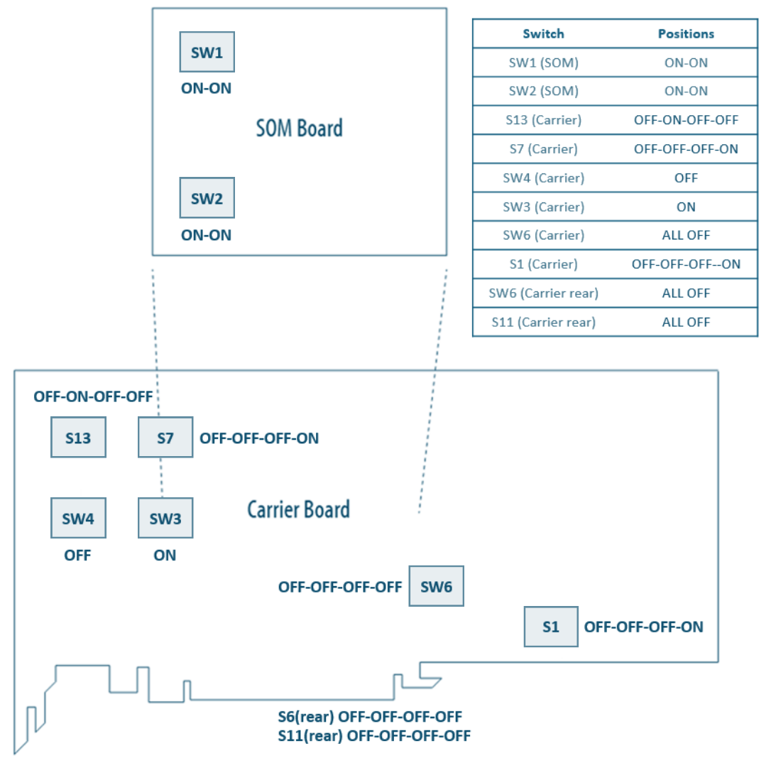
Development Board switch position
Main configurations used in this example design
JTAG: SOM SW1[1:0]=OFF:OFF
ASx4 (QSPI): SOM SW1[1:0]=ON:ON
ESD
Handle ESD-sensitive equipment (boards, microSD cards, camera sensors, etc.) only when properly grounded at an ESD-safe workstation.
- Connect the Framos cable between the Framos FSM:GO IMX678C Camera Modules and the MIPI connector on the modular development kit SOM (
MIPI0). Align pin 1 on the flex cable with pin 1 on the connector. - Connect a DisplayPort or HDMI display to the development kit when validating the ISP and display pipeline (
J16). - Connect micro USB cable from bottom right of the SOM board to PC
(
J2, HPS_UART). This will be used for HPS UART communication and JTAG terminal for FPGA programming. Look at what ports are enumerated on your host computer. Use the new one in the list as the HPS serial port (see figure below). - Connect an ethernet cable to the ethernet port on the SOM board (
J6, ETH 1G HPS) and make sure your device is in the same network as your intended host device. After Linux boots, check the IP address of theend2ethernet interface using theip addrcommand.
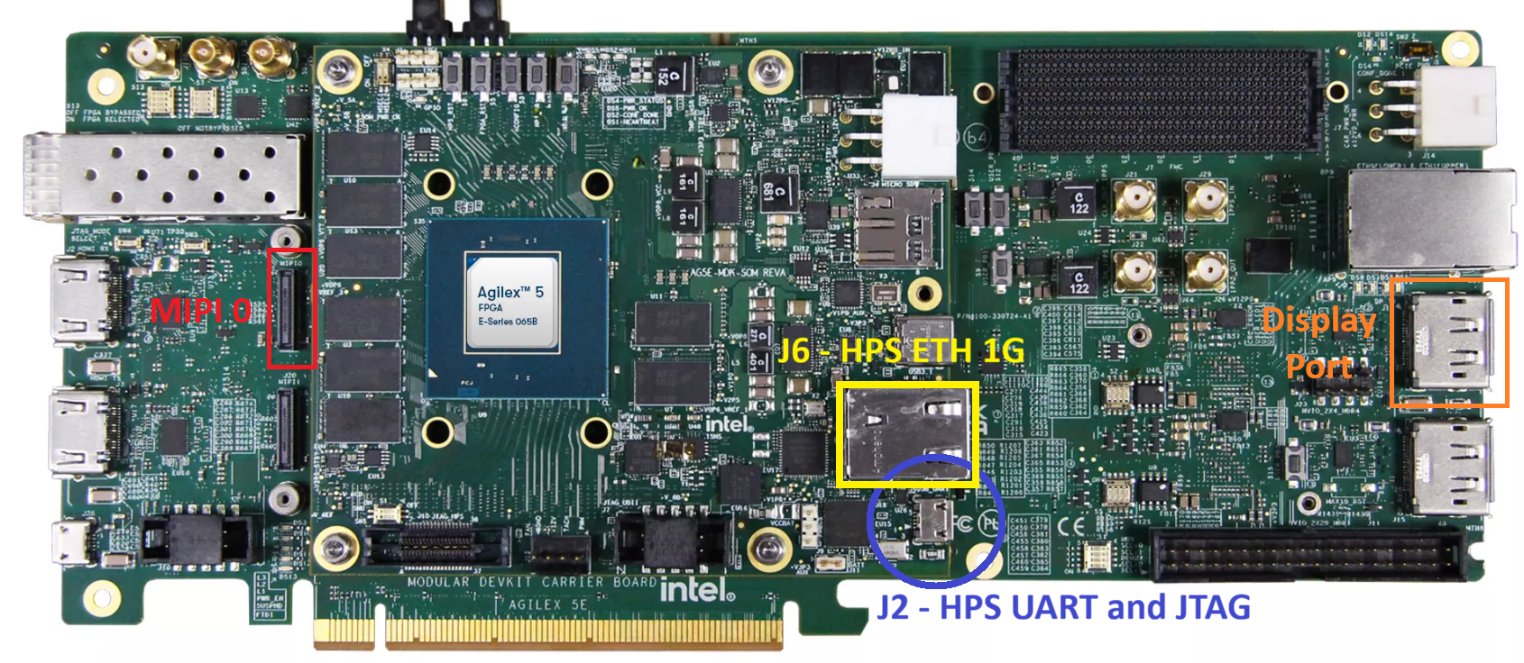
USB connections to the board
SD Card Image Flashing
- Download SD card image (
.wicor.wic.gz) from the prebuilt binary links above. - Write the
.wicor.wic.gzSD card image to the micro SD card using one of the options below. - Turn off the board and insert the SD card in the micro SD card slot on the SOM board.
USBImager (Windows, Linux, Mac OS)
- Open USBImager and click the
...button in the top right. - Select the image you downloaded earlier and click
Open. - Next select the device associated with your SD card reader from the drop-down list.
- Click
Writeto start flashing.
bmaptool (Linux)
Note
You will require a .wic.bmap file in addition to the .wic or .wic.gz in order to use bmaptool. If this is not available use USBImager.
On many distributions bmap-tools can be installed using your distros package manager (e.g. sudo apt install bmap-tools).
For more information see the Yocto documentation for bmaptool.
First of all determine the device logical name associated with the SD card on your host:
Use bmaptool to copy the image to the SD card. Make sure the wic image file and bmap file are in the same directory.
For example:
Flash the QSPI
- Download the
.jicimage from the prebuilt binary links above. - Power down the board.
- Set MSEL dipswitch S1 on SOM to JTAG: OFF-OFF
- Power up the board.
- Program the QSPI with the following command. See: quartus_pgm command
-
(Optional) Use the Quartus® Programmer GUI
- Launch the Quartus® Programmer and Configure the "Hardware Setup..." and select the SOM device (SM27 MDK OB-SOM UBIII)
- Click "Auto Detect", select the device
A5ED065BB32Aand press "Change File.."
- Select the
.jicfile you downloaded earlier. TheMT25QU02Gdevice should now show. Select the "Program/Configure" box, and press "Start". Wait until completed (It could take several minutes).
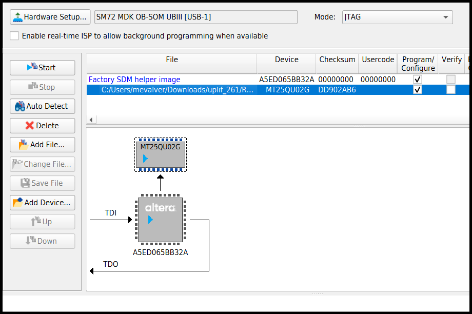
- Power down the board. Set MSEL dip switch S1 on SOM to ASX4 (QSPI): ON-ON
Bring Up the board
- Power up the board and set up the serial terminal (minicom, PuTTY, etc.):
- Select the correct
COMxport from the HPS serial UART. - Serial Port configuration:
- Baud rate: 115200, Data bits: 8, Stop bits: 1, CRC: disabled, Hardware flow control: disabled
- Connect your terminal emulator.
- Select the correct
- Wait for Linux to boot. Login password =
root.
Pull the Altera® ROS2 Docker Image
Run the following on the development kit HPS to pull the latest Altera® ROS2 Docker image.
Note
An internet connection is required to run the following commands.
The Docker image alterafpga/ros2 should now be listed when you run the following command.
The Docker image includes the Altera ROS 2 packages and examples pre-installed and ready to use.
Run the Altera® Camera ROS node
Next, run the Altera® Camera ROS node in a Docker container on the HPS. The node is a C++ ROS 2 publisher that reads frames from the ISP Robotics subsystem and publishes sensor_msgs/CameraInfo and sensor_msgs/msg/Image messages.
You can use the altera_camera.launch.py launch file provided by the altera_camera ROS package to start an instance of the node and start publishing frames from the FPGA video pipeline with ROS 2.
On the HPS, start a container using the image pulled in the previous section:
Note that the container is run with host networking passthrough mode so the board can communicate to other machines on the same LAN.We also pass through the ISP Robotics subsystem frame writer devices which appear as Userspace I/O (UIO) devices in Linux. uio0 is the BGR color stream and uio1 is the greyscale stream.
Launch the example camera node:
By default this will use /dev/uio0. If you wish to publish the greyscale stream run the following:
Upon successful initialization, you should see output similar to the following:
[INFO] [launch]: Default logging verbosity is set to INFO
[INFO] [altera_camera_node-1]: process started with pid [29]
[altera_camera_node-1] [INFO] [1781794579.867108167] [altera_camera]: using default calibration URL
[altera_camera_node-1] [INFO] [1781794579.867396841] [altera_camera]: camera calibration URL: file:///root/.ros/camera_info/altera-camera.yaml
While the node runs, the DisplayPort output continues to show the mixed live and preview video from the FPGA for local monitoring independent of ROS 2.
View the published camera stream
To visualize the published stream on a host PC, you can use the RQT Image View ROS package which is included in the Altera® ROS2 Docker image.
You first need to ensure Docker is installed on your host PC.
It is recommended to install Rocker to run a container capable of launching graphical applications. Follow the Rocker installation instructions before proceeding.
Once you have Rocker installed pull the Altera® ROS2 Docker image.
Note
An internet connection is required to run the following commands.
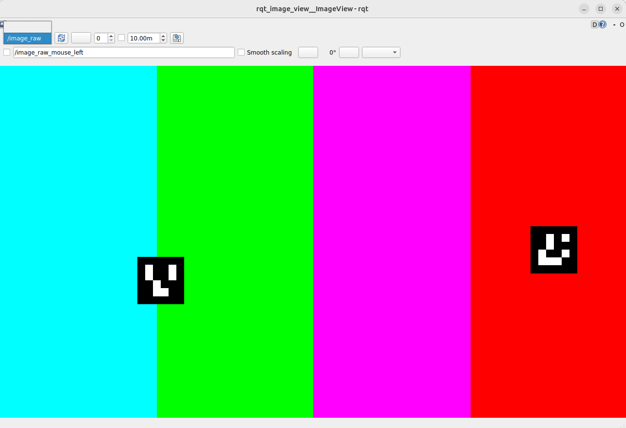
Next launch the rqt_image_view application in a Docker container on your host PC using the following command:
rocker --x11 --devices /dev/dri --network host alterafpga/ros2 ros2 run rqt_image_view rqt_image_view /image_raw
Note
The command above is for systems with Intel® integrated or discrete GPUs. On systems with an Nvidia® GPU, follow the Rocker Nvidia® steps and add the --nvidia flag.
You should see the live preview from the ISP Robotics video pipeline.
Recommended User Flows
With the available resources, you can build, compile, modify, and execute this design example. Additionally, there are two extra user flows that you can explore.
- User Flow 1: Getting Started — run with pre-built binaries.
- User Flow 2: Running the example design using the QAR and KAS.
- User Flow 3: Running the example design by creating and building with the Modular Design Toolkit (MDT) and KAS.
More resources.
| Source | Link |
|---|---|
| Pre-created QAR | ROBOTICS_ISP_CAMERA.qar |
| JIC / RBF | top.hps.jic, top.core.rbf |
| u-boot-spl-dtb.hex | u-boot-spl-dtb.hex |
Recommended User Flows.
| User Flow | Description | User flow 1 | User flow 2 | User flow 3 |
|---|---|---|---|---|
| Pre-requisites | Software Requirements to run. | |||
| Software Requirements to build. | ||||
| Hardware Requirements. | ||||
| Download the minimum Pre-built Binaries. | ||||
| HW-Compilation | Compile pre-created QAR with Quartus®. | |||
| Generating and Building the NiosV application and BSP. | ||||
| Creating and Building the Design based on Modular Design Toolkit (MDT). | ||||
Creating the QSPI Flash and SD card configuration bitstreams for the board (JIC/RBF). u-boot-spl-dtb.hex file, which is generated in the step below. |
||||
| SW-Compilation | Create SD card image (.wic) using YOCTO/KAS |
|||
| Programming | Setting Up your Development Board. | |||
| SD Card Image Flashing. | ||||
| Program the QSPI Flash Memory. | ||||
| Testing | Run the example design. |
Example Design Documentation
- Design Example Features.
- FPGA Hardware Functional Description.
- Software Stack Functional Description.
- Acronyms and Terminology.
Related Documentation
Example Designs
- Robot Controller with Vision System Example Design for Agilex™ 5 Devices
- ROS Consolidated Robot Controller Example Design for Agilex™ 5 Devices
- 4Kp60 Multi-Sensor HDR Camera Solution System Example Design for Agilex™ 5 Devices
- 4Kp30 Camera Lite Solution System Example Design for Agilex™ 3 Devices
- Drive-On-Chip with Functional Safety System Example Design for Agilex™ 5 Devices
- Drive-On-Chip with PLC System Example Design for Agilex™ Devices
- Agilex™ 5 FPGA - Drive-On-Chip Design Example
- Altera® Agilex™ 7 FPGA – Drive-On-Chip for Altera® Agilex™ 7 Devices Design Example
- Agilex™ 7 FPGA – Safe Drive-On-Chip Design Example
- Agilex™ 5 E-Series Modular Development Kit GSRD User Guide (26.1)
- Agilex™ 5 E-Series Modular Development Kit GHRD Linux Boot Examples
User Manuals
- Agilex™ 5 FPGA E-Series 065B Modular Development Kit
- Agilex™ 5 E-Series Modular Development Kit GSRD User Guide (26.1)
- Hard Processor System Technical Reference Manual: Agilex™ 5 SoCs (26.1)
- Framos FSM:GO IMX678C Camera Modules.
- Framos FFA-GMSL-SER-V2A Serializer.
- Framos FFA-GMSL-DES-V2A Deserializer.
- Video and Vision Processing Suite Altera® FPGA IP User Guide.
- VVP IP Suite.
- 3D LUT.
- MIPI DPHY IP and MIPI CSI-2 IP.
- Nios® V Processor.
Notices & Disclaimers
Altera® Corporation technologies may require enabled hardware, software or service activation. No product or component can be absolutely secure. Performance varies by use, configuration and other factors. Your costs and results may vary. You may not use or facilitate the use of this document in connection with any infringement or other legal analysis concerning Altera® products described herein. You agree to grant Altera® Corporation a non-exclusive, royalty-free license to any patent claim thereafter drafted which includes subject matter disclosed herein. No license (express or implied, by estoppel or otherwise) to any intellectual property rights is granted by this document, with the sole exception that you may publish an unmodified copy. You may create software implementations based on this document and in compliance with the foregoing that are intended to execute on the Altera® or product(s) referenced in this document. No rights are granted to create modifications or derivatives of this document. The products described may contain design defects or errors known as errata which may cause the product to deviate from published specifications. Current characterized errata are available on request. Altera® disclaims all express and implied warranties, including without limitation, the implied warranties of merchantability, fitness for a particular purpose, and non-infringement, as well as any warranty arising from course of performance, course of dealing, or usage in trade. You are responsible for safety of the overall system, including compliance with applicable safety-related requirements or standards. © Altera® Corporation. Altera®, the Altera logo, and other Altera® marks are trademarks of Altera® Corporation. Other names and brands may be claimed as the property of others.
OpenCL* and the OpenCL* logo are trademarks of Apple Inc. used by permission of the Khronos Group™.
Created: June 25, 2026