HPS GSRD User Guide
Introduction
Overview
The HPS Baseline System Example Design (formerly known as "GSRD" or "Golden System Reference Design") demonstrates basic HPS functionality on the Agilex 5 FPGA E-Series 065B Premium Development Kit.
The design is comprised of the following components:
- Quartus Design
- HPS software:
- Arm Trusted Firmware
- U-Boot
- Linux Kernel
- Linux Drivers
- Sample Applications
Prerequisites
The following are required to be able to fully exercise this System Example Design:
-
Altera® Agilex™ 5 FPGA E-Series 065B Premium Development Kit, ordering code DK-A5E065BB32AEA. Refer to board documentation for more information.
- HPS Enablement Expansion Board. Included with the development kit.
- HPS NAND Board. Enables eMMC and NAND storage options for HPS. Orderable separately.
- HPS Test Board. Supports SD card boot, and external Arm tracing. Orderable separately.
- Mini USB Cable. Included with the development kit.
- Micro USB Cable. Included with the development kit.
- Ethernet Cable. Included with the development kit.
- Micro SD card and USB card writer. Included with the development kit.
-
Host PC with:
- 64 GB of RAM. Less will be fine for only exercising the binaries, and not rebuilding the System Example Design.
- 200 GB of free disk space for Yocto buils
- Linux OS installed. Ubuntu 22.04LTS was used to create this page, other versions and distributions may work too
- Serial terminal (for example GtkTerm or Minicom on Linux and TeraTerm or PuTTY on Windows)
- Altera® Quartus® Prime Pro Edition Version 26.1
- TFTP server. This used to download the eMMC and NAND binaries to board to be flashed by U-Boot
- Local Ethernet network, with DHCP server
- Internet connection. For downloading the files, especially when rebuilding the System Example Design.
Prebuilt Binaries
The binaries for this system example design are located at https://releases.rocketboards.org/2026.04/:
| HPS Daughter Card | Boot Source | Link |
|---|---|---|
| Enablement Board | SD Card | https://releases.rocketboards.org/2026.04/gsrd/agilex5_dk_a5e065bb32aea_gsrd.baseline-a55/ |
| Enablement Board | QSPI | https://releases.rocketboards.org/2026.04/qspi/agilex5_dk_a5e065bb32aea_qspi.baseline-a55/ |
| NAND Board | eMMC | https://releases.rocketboards.org/2026.04/emmc/agilex5_dk_a5e065bb32aea_emmc.baseline-a55/ |
| NAND Board | NAND | https://releases.rocketboards.org/2026.04/nand/agilex5_dk_a5e065bb32aea_nand.baseline-a55/ |
| Test Board | SD Card | https://releases.rocketboards.org/2026.04/debug/agilex5_dk_a5e065bb32aea_debug.baseline-a55/ |
Component Versions
Altera® Quartus® Prime Pro Edition Version 26.1 and the following software component versions integrate the 26.1 release.
| Component | Location | Branch | Commit ID/Tag |
|---|---|---|---|
| Agilex 5 Design | https://github.com/altera-fpga/agilex5e-ed-gsrd | main | QPDS26.1_REL_GSRD_PR |
| Linux | https://github.com/altera-fpga/linux-socfpga | socfpga-6.18.2-lts | QPDS26.1_REL_GSRD_PR |
| Arm Trusted Firmware | https://github.com/altera-fpga/arm-trusted-firmware | socfpga_v2.14.0 | QPDS26.1_REL_GSRD_PR |
| U-Boot | https://github.com/altera-fpga/u-boot-socfpga | socfpga_v2026.01 | QPDS26.1_REL_GSRD_PR |
| Yocto Project | https://git.yoctoproject.org/poky | scarthgap | latest |
| Yocto meta-altera-fpga Layer | https://github.com/altera-fpga/meta-altera-fpga | scarthgap | QPDS26.1_REL_GSRD_PR |
Note: The combination of the component versions indicated in the table above has been validated through the use cases described in this page and it is strongly recommended to use these versions together. If you decided to use any component with different version than the indicated, there is not warranty that this will work.
Release Notes
See https://github.com/altera-fpga/gsrd-socfpga/releases/tag/QPDS26.1_REL_GSRD_PR
Development Kit
This design targets the * Altera® Agilex™ 5 FPGA E-Series 065B Premium Development Kit, ordering code DK-A5E065BB32AEA. Refer to board documentation for more information.
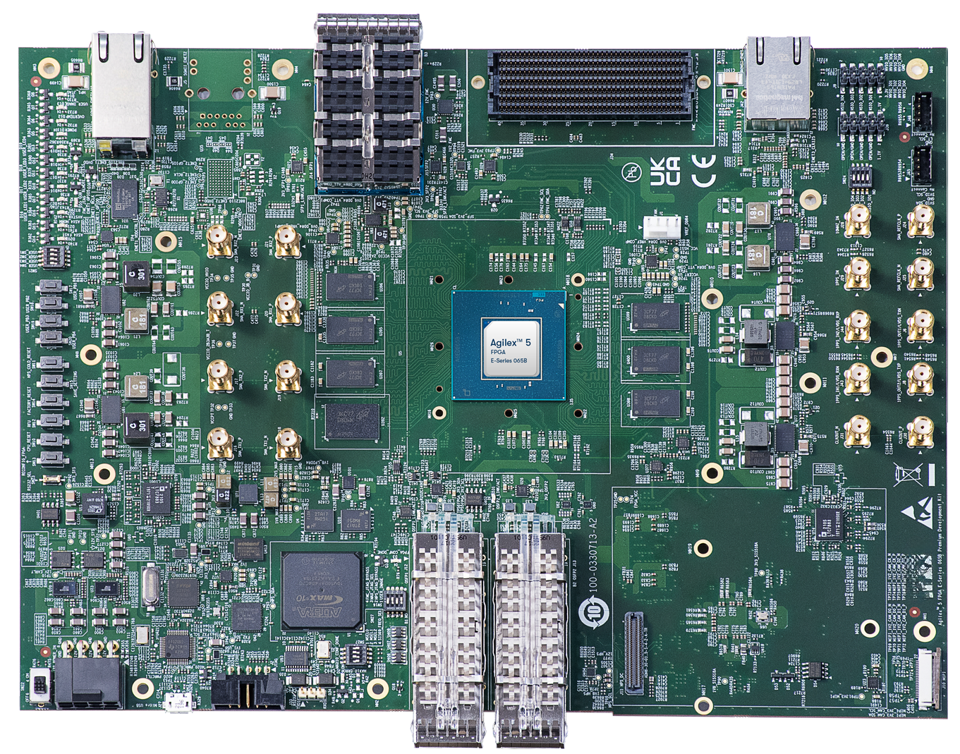
Installing HPS Daughtercard
This section shows how to install the included HPS Enablement Daughtercard. The installation for the other optional HPS Boards is similar.
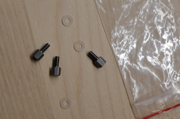
1. Identify the correct thumb screws and washers needed, they are in a plastic bag:
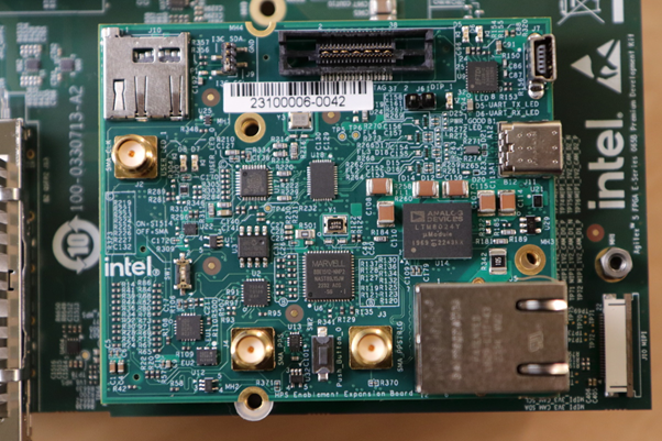
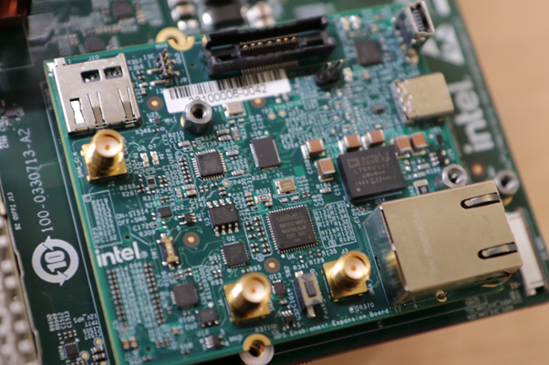
2. Locate the area on the development board where the HPS Daughtercard needs to be installed:
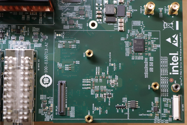
3. Place the plastic washers on top of the three hex mounting posts:
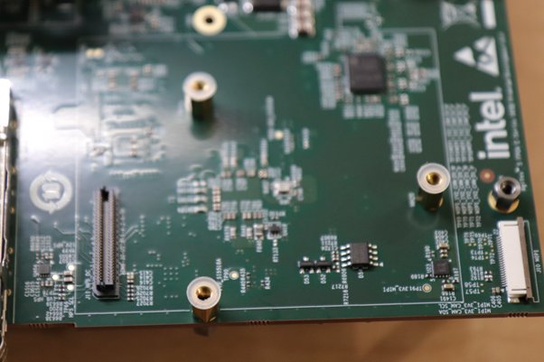
4. Place HPS Board on top of the posts and washers:
5. Place the hex thumb screws on the two posts, as shown below. Note the 3rd one on the bottom is best unplaced as fully screwing that in may move the board. Also note the thumb screw close to the Ethernet connector is hard to screw, recommend to use small pliers and patience to make it secure. It is important that the HPS Board is secure, and does not move:
Note: If you need to swap HPS Boards frequently, it is recommended to remove the hex posts, and install the plastic washers between the PCB and the posts. This way you do not need to be careful for the washers not to move when you place the HPS Board on top of the posts. Note there are also plastic washers underneath the development board PCB, make sure to leave those in place when performing this operation
Changing MSEL
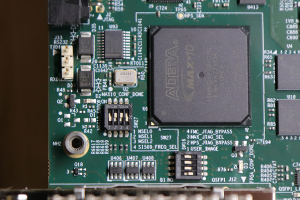
MSEL signals instruct the FPGA device on which configuration scheme to use. Configuration schemes used by the scenarios presented in this guide are JTAG and QSPI. MSEL is changed through dipswitch SW27. Only change the settings while the board is powered off.
Configuration OFF-OFF-OFF-OFF corresponds to JTAG:
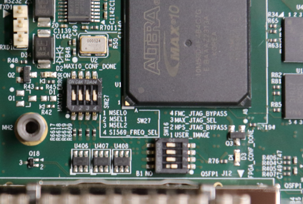
Configuration OFF-ON-ON-OFF corresponds to QSPI:
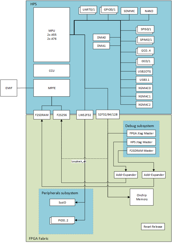
Quartus Design Overview
The Quartus Design is an important part of the HPS Baseline System Example Design and consists of the following components:
- Hard Processor System (HPS)
- Dual core Arm Cortex-A76 processor
- Dual core Arm Cortex-A55 processor
- HPS Peripherals connected to HPS Enablement Expansion Board:
- Micro SD Card
- EMAC
- HPS JTAG debug
- I3C
- UART
- USB 3.1
- Multi-Ported Front End (MPFE) for HPS External Memory Interface (EMIF)
- FPGA Peripherals connected to Lightweight HPS-to-FPGA (LWH2F) AXI Bridge and JTAG to Avalon Master Bridge
- Three user LED outputs
- Four user DIP switch inputs
- Four user push-button inputs
- System ID
- FPGA Peripherals connected to HPS-to-FPGA (H2F) AXI Bridge
- 256KB of FPGA on-chip memory
The HPS Baseline System Example Design allows hardware designers to access each peripheral in the FPGA portion of the SoC with System Console, through the JTAG master module. This signal-level access is independent of the driver readiness of each peripheral.
MPU Address Maps
This section presents the address maps as seen from the MPU side.
HPS-to-FPGA Address Map
The three FPGA windows in the MPU address map provide access to 256 GB of FPGA space. First window is 1 GB from 00_4000_0000, second window is 15 GB from 04_4000_0000, third window is 240 GB from 44_0000_0000. The following table lists the offset of each peripheral from the HPS-to-FPGA bridge in the FPGA portion of the SoC.
| Peripheral | Address Offset | Size (bytes) | Attribute |
|---|---|---|---|
| onchip_memory2_0 | 0x0 | 256K | On-chip RAM as scratch pad |
Lightweight HPS-to-FPGA Address Map
The the memory map of system peripherals in the FPGA portion of the SoC as viewed by the MPU, which starts at the lightweight HPS-to-FPGA base address of 0x00_2000_0000, is listed in the following table.
| Peripheral | Address Offset | Size (bytes) | Attribute |
|---|---|---|---|
| sysid | 0x0001_0000 | 32 | Unique system ID |
| led_pio | 0x0001_0080 | 16 | LED outputs |
| button_pio | 0x0001_0060 | 16 | Push button inputs |
| dipsw_pio | 0x0001_0070 | 16 | DIP switch inputs |
JTAG Master Address Map
There are three JTAG master interfaces in the design, one for accessing non-secure peripherals in the FPGA fabric, and another for accessing secure peripheral in the HPS through the FPGA-to-HPS Interface and another for FPGA fabric to SDRAM.
The following table lists the address of each peripheral in the FPGA portion of the SoC, as seen through the non-secure JTAG master interface.
| Peripheral | Address Offset | Size (bytes) | Attribute |
|---|---|---|---|
| onchip_memory2_0 | 0x0004_0000 | 256K | On-chip RAM |
| sysid | 0x0001_0000 | 32 | Unique system ID |
| led_pio | 0x0001_0080 | 16 | LED outputs |
| button_pio | 0x0001_0060 | 16 | Push button inputs |
| dipsw_pio | 0x0001_0070 | 16 | DIP switch inputs |
Interrupt Routing
The HPS exposes 64 interrupt inputs for the FPGA logic. The following table lists the interrupt connections from soft IP peripherals to the HPS interrupt input interface.
| Peripheral | Interrupt Number | Attribute |
|---|---|---|
| dipsw_pio | f2h_irq0[0] | 4 DIP switch inputs |
| button_pio | f2h_irq0[1] | 4 Push button inputs |
Exercise Prebuilt Binaries
This section presents how to use the prebuilt binaries included with this System Example Design
Configure Board
1. Leave all jumpers and switches in their default configuration.
2. Install the appropriate HPS Daughtercard.
3. Connect mini USB cable from vertical connector on HPS Daughtercard to host PC. This is used for the HPS serial console.
4. Connect micro USB cable from development board to host PC. This is used by the tools for JTAG communication.
5. Connect Ethernet cable from HPS Board to an Ethernet switch connected to local network. Local network must provide a DCHP server.
Configure Serial Console
All the scenarios included in this release require a serial connection. This section presents how to configure the serial connection.
1. Install a serial terminal emulator application on your host PC:
- For Windows: TeraTerm or PuTTY are available
- For Linux: GtkTerm or Minicom are available
2. Power down your board if powered up. This is important, as once powered up, with the micro USB JTAG cable connected, a couple more USB serial ports will enumerate, and you may choose the wrong port.
3. Connect mini-USB cable from the vertical mini-USB connector on the HPS Board to the host PC
4. On the host PC, an USB serial port will enumerate. On Windows machines it will be something like COM4, while on Linux machines it will be something like /dev/tty/USB0.
5. Configure your serial terminal emulator to use the following settings:
- Serial port: as mentioned above
- Baud rate: 115,200
- Data bits: 8
- Stop bits: 1
- CRC: disabled
- Hardware flow control: disabled
6. Connect your terminal emulator
HPS Enablement Board
This section presents how to use HPS Enablement Board to boot from SD card, and also from QSPI.
Boot from SD Card
Write SD Card
1. Download SD card image archive from the prebuilt binaries:
2. Extract the archive, obtaining the file gsrd-console-image-agilex5e.rootfs.wic
3. Write the `gsrd-console-image-agilex5e.rootfs.wic. SD card image to the micro SD card using the included USB writer in the host computer:
- On Linux, use the
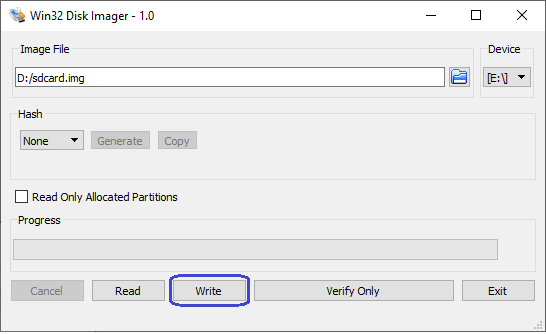
ddutility as shown next: - On Windows, use the Win32DiskImager program, available at https://sourceforge.net/projects/win32diskimager. For this, first rename the
gsrd-console-image-agilex5e.rootfs.wicto an.imgfile (sdcard.imgfor example) and write the image as shown in the next figure:
Write QSPI Flash
1. Power down board
2. Set MSEL dipswitch SW27 to JTAG: OFF-OFF-OFF-OFF
3. Power up the board
4. Download and extract the JIC image:
wget https://releases.rocketboards.org/2026.04/gsrd/agilex5_dk_a5e065bb32aea_gsrd.baseline-a55/ghrd.hps.jic
5. Write the JIC file to QSPI:
Boot Linux
1. Power down board
2. Set MSEL dipswitch SW27 to ASX4 (QSPi): OFF-ON-ON-OFF
3. Power up the board
4. Wait for Linux to boot, use root as user name, and no password wil be requested.
Connect to Board Using SSH
1. Boot to Linux
2. Determine the board IP address using the ifconfig command:
root@agilex5devkit:~# ifconfig
eth0: flags=-28605<UP,BROADCAST,RUNNING,MULTICAST,DYNAMIC> mtu 1500
inet 192.168.1.153 netmask 255.255.255.0 broadcast 192.168.1.255
inet6 fe80::f0eb:c8ff:fec4:eed7 prefixlen 64 scopeid 0x20<link>
ether f2:eb:c8:c4:ee:d7 txqueuelen 1000 (Ethernet)
RX packets 649 bytes 45132 (44.0 KiB)
RX errors 0 dropped 226 overruns 0 frame 0
TX packets 56 bytes 8789 (8.5 KiB)
TX errors 0 dropped 0 overruns 0 carrier 0 collisions 0
device interrupt 23
lo: flags=73<UP,LOOPBACK,RUNNING> mtu 65536
inet 127.0.0.1 netmask 255.0.0.0
inet6 ::1 prefixlen 128 scopeid 0x10<host>
loop txqueuelen 1000 (Local Loopback)
RX packets 100 bytes 8408 (8.2 KiB)
RX errors 0 dropped 0 overruns 0 frame 0
TX packets 100 bytes 8408 (8.2 KiB)
TX errors 0 dropped 0 overruns 0 carrier 0 collisions 0
root username, no password will be requested:
Note: Make sure to replace the above IP address to the one matching the output of running
ifconfigon youir board.
Run Sample Applications
1. Boot to Linux
2. Change current folder to alteraFPGA folder
syscheck application
Press q to exit the syscheck application.
Control LEDs Connected to FPGA Fabric
The following LEDs are exercised:
| Led Number | Silkscreen | Component |
|---|---|---|
| 0 | USER_LED1 | D16 |
| 1 | USER_LED2 | D17 |
| 2 | USER_LED3 | D18 |
Note: USER_LED4/D19 is quickly blinking, and cannot be controlled from software.
1. In order to blink an LED in a loop, with a specific delay in ms, run the following command:
- The led_number specifies the desired LED, and is a value between 0 and 3.
- The delay_ms is a number that specifies the desired delay in ms between turning the LED on and off.
2. In order to turn an individual LED on or off, run the following command:
- The led_number specifies the desired LED, and is a value between 0 and 3.
- The state needs to be 0 to turn the LED off, and 1 to turn the LED on.
3. In order to scroll the FPGA LEDs with a specific delay, please run the following command:
The delay specifies the desired scrolling behavior:
- delay > 0 - specify new scrolling delay in ms, and start scrolling
- delay < 0 - stop scrolling
- delay = 0 - display current scroll delay
You can also control the LEDs directly by accessing the following sysfs entries:
- /sys/class/leds/fpga_led0/brightness
- /sys/class/leds/fpga_led1/brightness
- /sys/class/leds/fpga_led2/brightness
using commands such as:
cat /sys/class/leds/fpga_led0/brightness
echo -e 0 > /sys/class/leds/fpga_led0/brightness
echo -e 1 > /sys/class/leds/fpga_led1/brightness
Visit Board Web Page
Important Note: By default, the web server functionality is not built into the image. You need to rebuild the System Example Design with the corresponding option enabled in Kas configuration Altera Linux Applications: LED Control. If you use the default image, the webserver will sever a simple page that says "It works!"
1. Boot to Linux
2. Determine board IP address using ifconfig like in the previous scenario
3. Start a web browser and enter the IP address in the address bar
4. The web browser will display a page served by the web server running on the board.
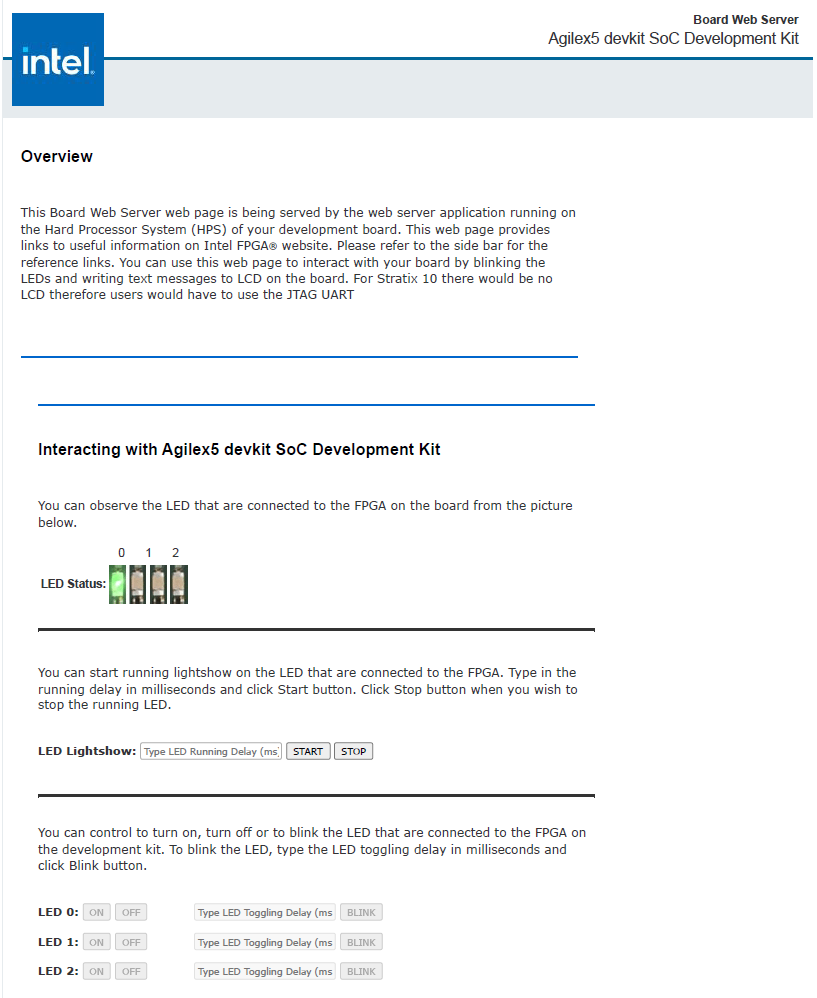
- You will able to see which LED are ON and OFF in LED Status.
- You can Start and Stop the LED from scrolling. Set the delay(ms) in the LED Lightshow box.
- You can controll each LED with ON and OFF button.
- Blink each LED by entering the delay(ms) and click on the BLINK button.
Boot from QSPI
This section presents how to boot from QSPI. One notable aspect is that you need to wipe the SD card partitioning information, as otherwise U-Boot SPL could find a valid SD card image, and try to boot from that first.
Wipe SD Card
Either write 1MB of zeroes at the beginning of the SD card, or remove the SD card from the HPS Daughter Card. You can use dd on Linux, or Win32DiskImager on Windows to achieve this.
Write QSPI Flash
1. Power down board
2. Set MSEL dipswitch SW27 to JTAG: OFF-OFF-OFF-OFF
3. Power up the board
4. Download and extract the JIC image:
wget https://releases.rocketboards.org/2026.04/qspi/agilex5_dk_a5e065bb32aea_qspi.baseline-a55/qspi_boot.hps.jic
jtagconfig --setparam 1 JtagClock 16M
quartus_pgm -c 1 -m jtag -o "pvi;qspi_boot.hps.jic"
5. Write JIC image to QSPI:
Boot Linux
1. Power down board
2. Set MSEL dipswitch SW27 to ASX4 (QSPi): OFF-ON-ON-OFF
3. Power up the board
4. Wait for Linux to boot, use root as user name, and no password wil be requested.
Note: On first boot, the UBIFS rootfilesystem is initialized, and that takes a few minutes. This will not happen on next reboots. See a sample log below:
[ 17.033558] UBIFS (ubi0:4): Mounting in unauthenticated mode
[ 17.039470] UBIFS (ubi0:4): background thread "ubifs_bgt0_4" started, PID 130
[ 17.061510] UBIFS (ubi0:4): start fixing up free space
[ 20.644496] random: crng init done
[ 27.120040] platform soc:leds: deferred probe pending
[ 243.190874] UBIFS (ubi0:4): free space fixup complete
[ 243.315909] UBIFS (ubi0:4): UBIFS: mounted UBI device 0, volume 4, name "rootfs"
[ 243.323290] UBIFS (ubi0:4): LEB size: 65408 bytes (63 KiB), min./max. I/O unit sizes: 8 bytes/256 bytes
[ 243.332653] UBIFS (ubi0:4): FS size: 167117440 bytes (159 MiB, 2555 LEBs), max 6500 LEBs, journal size
HPS NAND Board
This section presents how to use HPS NAND Board to boot from eMMC.
The eMMC and NAND binaries are written to flash using U-Boot helper JIC images, and require you to have a TFTP server for storing the files to be retrieved by the helper through the network.
Boot from eMMC
Configure Board
For this scenario, we are using the HPS NAND Board, which can be configured through dipswitch SW3 to enable either eMMC or NAND. Set SW3 to ON to enable eMMC.
Write eMMC Flash
We are writing the eMMC Flash by using U-Boot commands. We are getting to U-Boot prompt by booting from QSPI using a JIC image which contains U-Boot, thereby not relying on what is already in eMMC.
1. Download, and extract the eMMC image
wget https://releases.rocketboards.org/2026.04/emmc/agilex5_dk_a5e065bb32aea_emmc/sdimage.tar.gz
tar xf sdimage.tar.gz
xaa and xab on your TFTP folder.
3. Power down the board.
4. Set MSEL dipswitch SW27 to JTAG: OFF-OFF-OFF-OFF
5. Power up the board
6. Download the helper JIC used to write the eMMC image, extract it and write it to QSPI:
wget https://releases.rocketboards.org/2026.04/emmc/agilex5_dk_a5e065bb32aea_emmc/qspi_helper.hps.jic
jtagconfig --setparam 1 JtagClock 16M
quartus_pgm -c 1 -m jtag -o "pvi;qspi_helper.hps.jic"
ifconfig to use it as the IP address of the TFTP server
8. Power down the board
9. Set MSEL dipswitch SW27 to ASX4 (QSPi): OFF-ON-ON-OFF
10. Power up the board
11. Stop U-Boot at the boot countdown, to drop to U-Boot console
12. At the U-Boot console, run the following commands to write the SD card image:
setenv autoload no
dhcp
setenv serverip <tftp_server_ip_address>
tftp ${loadaddr} xaa
setexpr blkcnt1 ${filesize} / 0x200
mmc write ${loadaddr} 0 ${blkcnt1}
tftp ${loadaddr} xab
setexpr blkcnt2 ${filesize} / 0x200
mmc write ${loadaddr} ${blkcnt1} ${blkcnt2}
Write QSPI Flash
1. Power down the board.
2. Set MSEL dipswitch SW27 to JTAG: OFF-OFF-OFF-OFF
3. Power up the board
4. Download the JIC and write it to QSPI:
wget https://releases.rocketboards.org/2026.04/emmc/agilex5_dk_a5e065bb32aea_emmc/ghrd.hps.jic
jtagconfig --setparam 1 JtagClock 16M
quartus_pgm -c 1 -m jtag -o "pvi;ghrd.hps.jic"
Boot Linux
1. Power down the board.
2. Set MSEL dipswitch SW27 to ASX4 (QSPi): OFF-ON-ON-OFF
3. Power up the board
4. Board will boot to Linux. Enter root as username, no password will be requested
Boot from NAND
Configure Board
For this scenario, we are using the HPS NAND Board, which can be configured through dipswitch SW3 to enable either eMMC or NAND. Set SW3 to OFF to select NAND.
Write NAND Flash
We are writing the NAND Flash by using U-Boot commands. We are getting to U-Boot prompt by booting from QSPI using a JIC image which contains U-Boot.
1. Power down the board.
2. Set MSEL dipswitch SW27 to JTAG: OFF-OFF-OFF-OFF
3. Power up the board
4. Download the helper JIC used to write the NAND image, extract it and write it to QSPI:
wget https://releases.rocketboards.org/2026.04/nand/agilex5_dk_a5e065bb32aea_nand/qspi_helper.hps.jic
jtagconfig --setparam 1 JtagClock 16M
quartus_pgm -c 1 -m jtag -o "pvi;qspi_helper.hps.jic"
5. Power down the board.
6. Set MSEL dipswitch SW27 to ASX4 (QSPi): OFF-ON-ON-OFF
7. Power up the board and press any key to stop at U-Boot prompt
Important Note: The helper JIC image will try to boot first from NAND, if it finds something bootable in there, otherwise will boot from QSPI.
8. On your host machine, run ifconfig to determine your IP address. If you are running TFTP on another machine, determine the IP address of that machine.
9. Download the NAND binaries, and save them to your TFTP folder on the machine with the TFTP server:
wget https://releases.rocketboards.org/2026.04/nand/agilex5_dk_a5e065bb32aea_nand/u-boot.itb
wget https://releases.rocketboards.org/2026.04/nand/agilex5_dk_a5e065bb32aea_nand/root.ubi
cp u-boot-itb <tftp_folder>
cp root.ubi <tftp_folder>
10. At the U-Boot console, run the following commands to write the NAND binaries:
setenv autoload no
dhcp
setenv serverip <tftp_server_ip_address>

tftp $loadaddr u-boot.itb
nand erase.part u-boot
nand write $loadaddr u-boot $filesize

tftp $loadaddr root.ubi
nand erase.part clean root
nand write.trimffs $loadaddr root $filesize
Write QSPI Flash
1. Power down the board.
2. Set MSEL dipswitch SW27 to JTAG: OFF-OFF-OFF-OFF
3. Power up the board
4. Download the JIC and write it to QSPI:
wget https://releases.rocketboards.org/2026.04/nand/agilex5_dk_a5e065bb32aea_nand/ghrd.hps.jic
jtagconfig --setparam 1 JtagClock 16M
quartus_pgm -c 1 -m jtag -o "pvi;ghrd.hps.jic
Boot Linux
1. Power down the board.
2. Set MSEL dipswitch SW27 to ASX4 (QSPi): OFF-ON-ON-OFF
3. Power up the board
4. Board will boot to Linux. Enter root as username, no password will be requested
HPS Test Board
This section presents how to use HPS Test Board to boot from SD card.
Boot from SD Card
Configure Board
For this scenario we are using the HPS Test Board. There is single dipswitch on that board called SW1, which needs to be set to the ON position.
Write SD Card
1. Download SD card image from the prebuilt binaries https://releases.rocketboards.org/2026.04/debug/agilex5_dk_a5e065bb32aes1_debug/sdimage.tar.gz and extract the archive, obtaining the file gsrd-console-image-agilex5_devkit.wic.
2. Write the SD card image to the micro SD card using the included USB writer in the host computer, and dd utility on Linux, or Win32DiskImager on Windows, available at https://sourceforge.net/projects/win32diskimager. Please refer to the Boot from SD Card section for more details about this.
Write QSPI Flash
1. Power down the board.
2. Set MSEL dipswitch SW27 to JTAG: OFF-OFF-OFF-OFF
3. Power up the board
4. Download the JIC and write it to QSPI:
wget https://releases.rocketboards.org/2026.04/debug/agilex5_dk_a5e065bb32aes1_debug/ghrd_a5ed065bb32ae6sr0.hps.jic.tar.gz
tar xf ghrd_a5ed065bb32ae6sr0.hps.jic.tar.gz
jtagconfig --setparam 1 JtagClock 16M
quartus_pgm -c 1 -m jtag -o "pvi;ghrd_a5ed065bb32ae6sr0.hps.jic"
Boot Linux
1. Power down the board.
2. Set MSEL dipswitch SW27 to ASX4 (QSPi): OFF-ON-ON-OFF
3. Power up the board
4. Board will boot to Linux. Enter root as username, no password will be requested
Rebuild Binaries
The embedded software for this System Example Design is built with Yocto, using KAS.
Kas is a Python-based lightweight build orchestration layer on top of BitBake/Yocto. Kas allows you to define your build environment in a YAML manifest, so you can perform checkout, environment setup, configuration, and build invocation with a single command. Kas provides a more maintainable build description, it offers improved reproducibility, reduced setup friction, and a clearer abstraction for managing multiple layers, revisions, and configuration fragments.
The software source code for this System Example Design is released inside the software/yocto_linux directory. Accessing the link will display a README page with details regarding the software.
For more details about Kas, refer to the official documentation at https://kas.readthedocs.io/en/latest/.
Kas Build Prerequisites
Firtst, the same prerequisites as for regular Yocto build are required.
1. Make sure you have Yocto system requirements met: https://docs.yoctoproject.org/scarthgap/ref-manual/system-requirements.html#supported-linux-distributions.
The command to install the required packages on Ubuntu 22.04 is:
sudo apt-get update
sudo apt-get upgrade
sudo apt-get install openssh-server mc libgmp3-dev libmpc-dev gawk wget git diffstat unzip texinfo gcc \
build-essential chrpath socat cpio python3 python3-pip python3-pexpect xz-utils debianutils iputils-ping \
python3-git python3-jinja2 libegl1-mesa libsdl1.2-dev pylint xterm python3-subunit mesa-common-dev zstd \
liblz4-tool git fakeroot build-essential ncurses-dev xz-utils libssl-dev bc flex libelf-dev bison xinetd \
tftpd tftp nfs-kernel-server libncurses5 libc6-i386 libstdc++6:i386 libgcc++1:i386 lib32z1 \
device-tree-compiler curl mtd-utils u-boot-tools net-tools swig -y
On Ubuntu 22.04 you will also need to point the /bin/sh to /bin/bash, as the default is a link to /bin/dash:
Note: You can also use a Docker container to build the Yocto recipes, refer to https://rocketboards.org/foswiki/Documentation/DockerYoctoBuild for details. When using a Docker container, it does not matter what Linux distribution or packages you have installed on your host, as all dependencies are provided by the Docker container.
In addition to the above, you must also install python3-newt, and python3.10-venv with a command like this:
HPS Enablement Board
Build SD Card Binaries
The following diagram shows an overview of the building process:

Setup Environment
1. Create the top folder to store all the build artifacts:
sudo rm -rf agilex5_065b_base.sd
mkdir agilex5_065b_base.sd
cd agilex5_065b_base.sd
export TOP_FOLDER=`pwd`
Enable Quartus tools to be called from command line:
Build Quartus Design
cd $TOP_FOLDER
rm -rf agilex5_soc_devkit_ghrd && mkdir agilex5_soc_devkit_ghrd && cd agilex5_soc_devkit_ghrd
wget https://github.com/altera-fpga/agilex5e-ed-gsrd/releases/download/QPDS26.1_REL_GSRD_PR/a5ed065b-premium-devkit-oobe-baseline-a55.zip
unzip a5ed065b-premium-devkit-oobe-baseline-a55.zip
rm -f a5ed065b-premium-devkit-oobe-baseline-a55.zip
make baseline_a55-install
The following files are created:
$TOP_FOLDER/agilex5_soc_devkit_ghrd/install/binaries/baseline_a55.sof$TOP_FOLDER/agilex5_soc_devkit_ghrd/install/binaries/baseline_a55_hps_debug.sof$TOP_FOLDER/agilex5_soc_devkit_ghrd/install/binaries/ghrd.core.rbf
Build Yocto Using Kas
1. Create and enter a new Python virtual environment:
cd $TOP_FOLDER/agilex5_soc_devkit_ghrd/software/yocto_linux
python3 -m venv venv --system-site-packages
source venv/bin/activate
pip install --upgrade pip
pip install kas
pip install --upgrade kas
pip install kconfiglib
2. Copy the core.rbf file to where Kas expects it to be:
cp $TOP_FOLDER/agilex5_soc_devkit_ghrd/install/binaries/ghrd.core.rbf \
   $TOP_FOLDER/agilex5_soc_devkit_ghrd/software/yocto_linux/meta-custom/recipes-fpga/fpga-bitstream/files/baseline_a55_hps_debug.core.rbf
3. Build Yocto with Kas:
The following relevant files are created in $TOP_FOLDER/agilex5_soc_devkit_ghrd/software/yocto_linux/build/tmp/deploy/images/agilex5e/:
gsrd-console-image-agilex5e.rootfs.wicu-boot-spl-dtb.hex
Note: If you experience build failures related to file-locks, you can work around these by reducing the parallelism of your build by running the following commands before running
kas:
export PARALLEL_MAKE="-j 8"
export BB_NUMBER_THREADS="8"
export BB_ENV_PASSTHROUGH_ADDITIONS="$BB_ENV_PASSTHROUGH_ADDITIONS PARALLEL_MAKE BB_NUMBER_THREADS"
Build QSPI Image
cd $TOP_FOLDER
rm -f baseline.hps.jic baseline.core.rbf
quartus_pfg \
-c agilex5_soc_devkit_ghrd/install/binaries/baseline_a55.sof baseline.jic \
-o device=MT25QU128 \
-o flash_loader=A5ED065BB32AE4S \
-o hps_path=agilex5_soc_devkit_ghrd/software/yocto_linux/build/tmp/deploy/images/agilex5e/u-boot-spl-dtb.hex \
-o mode=ASX4 \
-o hps=1
The following file is created:
$TOP_FOLDER/baseline.hps.jic
Build QSPI Binaries
The following diagram shows an overview of the building process:

Setup Environment
1. Create the top folder to store all the build artifacts:
sudo rm -rf agilex5_065b_base.qspi
mkdir agilex5_065b_base.qspi
cd agilex5_065b_base.qspi
export TOP_FOLDER=`pwd`
Enable Quartus tools to be called from command line:
Build Quartus Design
cd $TOP_FOLDER
rm -rf agilex5_soc_devkit_ghrd && mkdir agilex5_soc_devkit_ghrd && cd agilex5_soc_devkit_ghrd
wget https://github.com/altera-fpga/agilex5e-ed-gsrd/releases/download/QPDS26.1_REL_GSRD_PR/a5ed065b-premium-devkit-oobe-baseline-a55.zip
unzip a5ed065b-premium-devkit-oobe-baseline-a55.zip
rm -f a5ed065b-premium-devkit-oobe-baseline-a55.zip
make baseline_a55-install
The following files are created:
$TOP_FOLDER/agilex5_soc_devkit_ghrd/install/binaries/baseline_a55.sof$TOP_FOLDER/agilex5_soc_devkit_ghrd/install/binaries/baseline_a55_hps_debug.sof$TOP_FOLDER/agilex5_soc_devkit_ghrd/install/binaries/ghrd.core.rbf
Build Yocto Using Kas
1. Create and enter a new Python virtual environment. A virtual environment allows you to install packages without impacting your global environment:
cd $TOP_FOLDER/agilex5_soc_devkit_ghrd/software/yocto_linux
python3 -m venv venv --system-site-packages
source venv/bin/activate
pip install --upgrade pip
pip install kas
pip install --upgrade kas
pip install kconfiglib
2. Copy the core.rbf file to where Kas expects it to be:
cp $TOP_FOLDER/agilex5_soc_devkit_ghrd/install/binaries/ghrd.core.rbf \
   $TOP_FOLDER/agilex5_soc_devkit_ghrd/software/yocto_linux/meta-custom/recipes-fpga/fpga-bitstream/files/baseline_a55_hps_debug.core.rbf
3. Build Yocto with Kas:
Note: If you wish to customize your Linux image, you can use the
kas menucommand instead. The options here are explained in section Customizing Yocto Kas Build below.
The following relevant files are created in $TOP_FOLDER/agilex5_soc_devkit_ghrd/software/yocto_linux/build/tmp/deploy/images/agilex5e/:
u-boot-spl-dtb.hexu-boot.itbcore-image-minimal-agilex5e.rootfs_nor.ubifskernel.itbboot.scr.uimg
Build QSPI Image
1. Create the folder to contain all the files:
2. Link to the files that are needed from building the Quartus Design, and Yocto:
ln -s $TOP_FOLDER/agilex5_soc_devkit_ghrd/install/binaries/baseline_a55.sof ghrd.sof
ln -s $TOP_FOLDER/agilex5_soc_devkit_ghrd/software/yocto_linux/build/tmp/deploy/images/agilex5e/u-boot-spl-dtb.hex .
ln -s $TOP_FOLDER/agilex5_soc_devkit_ghrd/software/yocto_linux/build/tmp/deploy/images/agilex5e/u-boot.itb u-boot.bin
ln -s $TOP_FOLDER/agilex5_soc_devkit_ghrd/software/yocto_linux/build/tmp/deploy/images/agilex5e/console-image-minimal-agilex5e.rootfs_nor.ubifs .
ln -s $TOP_FOLDER/agilex5_soc_devkit_ghrd/software/yocto_linux/build/tmp/deploy/images/agilex5e/kernel.itb .
ln -s $TOP_FOLDER/agilex5_soc_devkit_ghrd/software/yocto_linux/build/tmp/deploy/images/agilex5e/boot.scr.uimg .
ln -s $TOP_FOLDER/agilex5_soc_devkit_ghrd/software/yocto_linux/build/tmp/deploy/images/agilex5e/uboot.env .
ln -s $TOP_FOLDER/agilex5_soc_devkit_ghrd/software/yocto_linux/scripts/ubinize_nor.cfg .
ln -s $TOP_FOLDER/agilex5_soc_devkit_ghrd/software/yocto_linux/scripts/qspi_boot.pfg .
3. Create the root.ubi file and rename it to hps.bin as Programming File Generator needs the .bin extension:
4. Create the JIC file:
The following file will be created:
$TOP_FOLDER/qspi_boot/qspi_boot.hps.jic
HPS NAND Board
Build eMMC Binaries
The following diagram shows an overview of the building process:
Setup Environment
1. Create the top folder to store all the build artifacts:
sudo rm -rf agilex5_065b_base.emmc
mkdir agilex5_065b_base.emmc
cd agilex5_065b_base.emmc
export TOP_FOLDER=`pwd`
Enable Quartus tools to be called from command line:
Build Quartus Design
cd $TOP_FOLDER
rm -rf agilex5_soc_devkit_ghrd && mkdir agilex5_soc_devkit_ghrd && cd agilex5_soc_devkit_ghrd
wget https://github.com/altera-fpga/agilex5e-ed-gsrd/releases/download/QPDS26.1_REL_GSRD_PR/a5ed065b-premium-devkit-emmc-baseline-a55.zip
unzip a5ed065b-premium-devkit-emmc-baseline-a55.zip
rm -f a5ed065b-premium-devkit-emmc-baseline-a55.zip
make baseline_a55-install
The following files are created:
$TOP_FOLDER/agilex5_soc_devkit_ghrd/install/binaries/baseline_a55.sof$TOP_FOLDER/agilex5_soc_devkit_ghrd/install/binaries/baseline_a55_hps_debug.sof$TOP_FOLDER/agilex5_soc_devkit_ghrd/install/binaries/ghrd.core.rbf
Build Yocto Using Kas
1. Create and enter a new Python virtual environment:
cd $TOP_FOLDER/agilex5_soc_devkit_ghrd/software/yocto_linux
python3 -m venv venv --system-site-packages
source venv/bin/activate
pip install --upgrade pip
pip install kas
pip install --upgrade kas
pip install kconfiglib
2. Copy the core.rbf file to where Kas expects it to be:
cp $TOP_FOLDER/agilex5_soc_devkit_ghrd/install/binaries/ghrd.core.rbf \
   $TOP_FOLDER/agilex5_soc_devkit_ghrd/software/yocto_linux/meta-custom/recipes-fpga/fpga-bitstream/files/baseline_a55_hps_debug.core.rbf
3. Build Yocto with Kas:
The following relevant files are created in $TOP_FOLDER/agilex5_soc_devkit_ghrd/software/yocto_linux/build/tmp/deploy/images/agilex5e/:
gsrd-console-image-agilex5e.rootfs.wicu-boot-spl-dtb.hex
Note: If you experience build failures related to file-locks, you can work around these by reducing the parallelism of your build by running the following commands before running
kas:
export PARALLEL_MAKE="-j 8"
export BB_NUMBER_THREADS="8"
export BB_ENV_PASSTHROUGH_ADDITIONS="$BB_ENV_PASSTHROUGH_ADDITIONS PARALLEL_MAKE BB_NUMBER_THREADS"
Build QSPI Image
cd $TOP_FOLDER
rm -f baseline.hps.jic baseline.core.rbf
quartus_pfg \
-c agilex5_soc_devkit_ghrd/install/binaries/baseline_a55.sof baseline.jic \
-o device=MT25QU128 \
-o flash_loader=A5ED065BB32AE4S \
-o hps_path=agilex5_soc_devkit_ghrd/software/yocto_linux/build/tmp/deploy/images/agilex5e/u-boot-spl-dtb.hex \
-o mode=ASX4 \
-o hps=1
The following file is created:
$TOP_FOLDER/baseline.hps.jic
Build QSPI Helper Image
cd $TOP_FOLDER
rm -rf qspi_helper && mkdir qspi_helper && cd qspi_helper
ln -s ../agilex5_soc_devkit_ghrd/install/binaries/baseline_a55.sof ghrd.sof
ln -s ../agilex5_soc_devkit_ghrd/software/yocto_linux/build/tmp/deploy/images/agilex5e/u-boot-spl-dtb.hex u-boot-spl-dtb.hex
ln -s ../agilex5_soc_devkit_ghrd/software/yocto_linux/build/tmp/deploy/images/agilex5e/u-boot.itb u-boot.bin
ln -s ../agilex5_soc_devkit_ghrd/software/yocto_linux/scripts/qspi_helper.pfg .
quartus_pfg -c qspi_helper.pfg
The following file is created:
$TOP_FOLDER/qspi_helper/qspi_helper.hps.jic
Build NAND Binaries
The following diagram shows an overview of the building process:

Setup Environment
1. Create the top folder to store all the build artifacts:
sudo rm -rf agilex5_065b_base.nand
mkdir agilex5_065b_base.nand
cd agilex5_065b_base.nand
export TOP_FOLDER=`pwd`
Enable Quartus tools to be called from command line:
Build Quartus Design
cd $TOP_FOLDER
rm -rf agilex5_soc_devkit_ghrd && mkdir agilex5_soc_devkit_ghrd && cd agilex5_soc_devkit_ghrd
wget https://github.com/altera-fpga/agilex5e-ed-gsrd/releases/download/QPDS26.1_REL_GSRD_PR/a5ed065b-premium-devkit-nand-baseline-a55.zip
unzip a5ed065b-premium-devkit-nand-baseline-a55.zip
rm -f a5ed065b-premium-devkit-nand-baseline-a55.zip
make baseline_a55-install
The following files are created:
$TOP_FOLDER/agilex5_soc_devkit_ghrd/install/binaries/baseline_a55.sof$TOP_FOLDER/agilex5_soc_devkit_ghrd/install/binaries/baseline_a55_hps_debug.sof$TOP_FOLDER/agilex5_soc_devkit_ghrd/install/binaries/ghrd.core.rbf
Build Yocto Using Kas
1. Create and enter a new Python virtual environment:
cd $TOP_FOLDER/agilex5_soc_devkit_ghrd/software/yocto_linux
python3 -m venv venv --system-site-packages
source venv/bin/activate
pip install --upgrade pip
pip install kas
pip install --upgrade kas
pip install kconfiglib
2. Copy the core.rbf file to where Kas expects it to be:
cp $TOP_FOLDER/agilex5_soc_devkit_ghrd/install/binaries/ghrd.core.rbf \
   $TOP_FOLDER/agilex5_soc_devkit_ghrd/software/yocto_linux/meta-custom/recipes-fpga/fpga-bitstream/files/baseline_a55_hps_debug.core.rbf
3. Build Yocto with Kas:
The following relevant files are created in $TOP_FOLDER/agilex5_soc_devkit_ghrd/software/yocto_linux/build/tmp/deploy/images/agilex5e/:
gsrd-console-image-agilex5e.rootfs.wicu-boot.itbu-boot-spl-dtb.hex
Note: If you experience build failures related to file-locks, you can work around these by reducing the parallelism of your build by running the following commands before running
kas:
export PARALLEL_MAKE="-j 8"
export BB_NUMBER_THREADS="8"
export BB_ENV_PASSTHROUGH_ADDITIONS="$BB_ENV_PASSTHROUGH_ADDITIONS PARALLEL_MAKE BB_NUMBER_THREADS"
Build root.ubi Image
cd $TOP_FOLDER
rm -rf nand_images && mkdir nand_images && cd nand_images
ln -s ../agilex5_soc_devkit_ghrd/software/yocto_linux/build/tmp/deploy/images/agilex5e/u-boot.itb
ln -s ../agilex5_soc_devkit_ghrd/software/yocto_linux/scripts/ubinize_nand.cfg .
ln -s ../agilex5_soc_devkit_ghrd/software/yocto_linux/build/tmp/deploy/images/agilex5e/uboot.env .
ln -s ../agilex5_soc_devkit_ghrd/software/yocto_linux/build/tmp/deploy/images/agilex5e/boot.scr.uimg .
ln -s ../agilex5_soc_devkit_ghrd/software/yocto_linux/build/tmp/deploy/images/agilex5e/kernel.itb .
ln -s ../agilex5_soc_devkit_ghrd/software/yocto_linux/build/tmp/deploy/images/agilex5e/console-image-minimal-agilex5e.rootfs_nand.ubifs .
ubinize -o root.ubi -p 1024KiB -m 8192 -s 8192 ubinize_nand.cfg
The following file is created:
$TOP_FOLDER/nand_images/root.ubi
Build QSPI Image
cd $TOP_FOLDER
rm -f baseline.hps.jic baseline.core.rbf
quartus_pfg \
-c agilex5_soc_devkit_ghrd/install/binaries/baseline_a55.sof baseline.jic \
-o device=MT25QU128 \
-o flash_loader=A5ED065BB32AE4S \
-o hps_path=agilex5_soc_devkit_ghrd/software/yocto_linux/build/tmp/deploy/images/agilex5e/u-boot-spl-dtb.hex \
-o mode=ASX4 \
-o hps=1
The following file is created:
$TOP_FOLDER/baseline.hps.jic
Build QSPI Helper Image
cd $TOP_FOLDER
rm -rf qspi_helper && mkdir qspi_helper && cd qspi_helper
ln -s ../agilex5_soc_devkit_ghrd/install/binaries/baseline_a55.sof ghrd.sof
ln -s ../agilex5_soc_devkit_ghrd/software/yocto_linux/build/tmp/deploy/images/agilex5e/u-boot-spl-dtb.hex u-boot-spl-dtb.hex
ln -s ../agilex5_soc_devkit_ghrd/software/yocto_linux/build/tmp/deploy/images/agilex5e/u-boot.itb u-boot.bin
ln -s ../agilex5_soc_devkit_ghrd/software/yocto_linux/scripts/qspi_helper.pfg .
quartus_pfg -c qspi_helper.pfg
The following file is created:
$TOP_FOLDER/qspi_helper/qspi_helper.hps.jic
HPS Test Board
Build SD Card Binaries
The following diagram shows an overview of the building process:
Setup Environment
1. Create the top folder to store all the build artifacts:
sudo rm -rf agilex5_065b_base.test
mkdir agilex5_065b_base.test
cd agilex5_065b_base.test
export TOP_FOLDER=`pwd`
Enable Quartus tools to be called from command line:
Build Quartus Design
cd $TOP_FOLDER
rm -rf agilex5_soc_devkit_ghrd && mkdir agilex5_soc_devkit_ghrd && cd agilex5_soc_devkit_ghrd
wget https://github.com/altera-fpga/agilex5e-ed-gsrd/releases/download/QPDS26.1_REL_GSRD_PR/a5ed065b-premium-devkit-debug2-baseline-a55.zip
unzip a5ed065b-premium-devkit-debug2-baseline-a55.zip
rm -f a5ed065b-premium-devkit-debug2-baseline-a55.zip
make baseline_a55-install
The following files are created:
$TOP_FOLDER/agilex5_soc_devkit_ghrd/install/binaries/baseline_a55.sof$TOP_FOLDER/agilex5_soc_devkit_ghrd/install/binaries/baseline_a55_hps_debug.sof$TOP_FOLDER/agilex5_soc_devkit_ghrd/install/binaries/ghrd.core.rbf
Build Yocto Using Kas
1. Create and enter a new Python virtual environment:
cd $TOP_FOLDER/agilex5_soc_devkit_ghrd/software/yocto_linux
python3 -m venv venv --system-site-packages
source venv/bin/activate
pip install --upgrade pip
pip install kas
pip install --upgrade kas
pip install kconfiglib
2. Copy the core.rbf file to where Kas expects it to be:
cp $TOP_FOLDER/agilex5_soc_devkit_ghrd/install/binaries/ghrd.core.rbf \
   $TOP_FOLDER/agilex5_soc_devkit_ghrd/software/yocto_linux/meta-custom/recipes-fpga/fpga-bitstream/files/baseline_a55_hps_debug.core.rbf
3. Build Yocto with Kas:
The following relevant files are created in $TOP_FOLDER/agilex5_soc_devkit_ghrd/software/yocto_linux/build/tmp/deploy/images/agilex5e/:
gsrd-console-image-agilex5e.rootfs.wicu-boot-spl-dtb.hex
Note: If you experience build failures related to file-locks, you can work around these by reducing the parallelism of your build by running the following commands before running
kas:
export PARALLEL_MAKE="-j 8"
export BB_NUMBER_THREADS="8"
export BB_ENV_PASSTHROUGH_ADDITIONS="$BB_ENV_PASSTHROUGH_ADDITIONS PARALLEL_MAKE BB_NUMBER_THREADS"
Build QSPI Image
cd $TOP_FOLDER
rm -f baseline.hps.jic baseline.core.rbf
quartus_pfg \
-c agilex5_soc_devkit_ghrd/install/binaries/baseline_a55.sof baseline.jic \
-o device=MT25QU128 \
-o flash_loader=A5ED065BB32AE4S \
-o hps_path=agilex5_soc_devkit_ghrd/software/yocto_linux/build/tmp/deploy/images/agilex5e/u-boot-spl-dtb.hex \
-o mode=ASX4 \
-o hps=1
The following file is created:
$TOP_FOLDER/baseline.hps.jic
Additional Guides
Customize Kas Build
The kas.yml file is the central configuration file used by Kas to define all components required for a reproducible Yocto build environment. It specifies the repositories, branches, layers, and build targets, as well as optional environment variables and machine settings. By consolidating this information into a single YAML file, kas.yml eliminates manual setup steps and ensures that builds can be easily replicated across systems or shared with collaborators. This makes it an essential part of version-controlled, automated build workflows.
Kas also offers Kconfig-based customizations to provide a flexible and user-friendly configuration experience. This enables you to select repositories, layers, and build targets through a structured menu interface instead of editing YAML files directly. This approach combines the clarity and reproducibility of Kas with the modular configurability of the Linux kernel?s Kconfig system, making it easier to tailor builds for different platforms or use cases while maintaining a consistent and automated setup.
Review the kas.yml file, the Kconfig options and associated documentation at https://github.com/altera-fpga/agilex5e-ed-gsrd/tree/QPDS26.1_REL_GSRD_PR/a5ed065b-premium-devkit-oobe/baseline-a55/software/yocto_linux.
In the build instructions we did not use the Kconfig options, only the default options from kas.yml were used. This section shows how you can use kas menu to customize the build.
When using kas menu, the initial settings from kas.yml are customized with the user selected options through Kconfig, and are saved to a file called .config.yaml which is then used for build purposes.
1. Build the Quartus Design as mentioned before. Note the same Quartus Design is used for both booting from SD card and booting from QSPI.
2. Copy the core.rbf file to where Kas needs it to be:
cp $TOP_FOLDER/agilex5_soc_devkit_ghrd/install/binaries/ghrd.core.rbf \
   $TOP_FOLDER/agilex5_soc_devkit_ghrd/software/yocto_linux/meta-custom/recipes-fpga/fpga-bitstream/files/baseline_a55_hps_debug.core.rbf
3. Create an enter a new Python virtual environment, not to interfere with the current system Python packages:
cd $TOP_FOLDER/agilex5_soc_devkit_ghrd/software/yocto_linux
python3 -m venv venv --system-site-packages
source venv/bin/activate
pip install --upgrade pip
pip install kas
pip install --upgrade kas
pip install kconfiglib
4. Run kas menu:
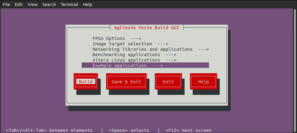
5. You will be presented with a Kconfig text menu, similar to the ones from Linux Kernel & U-Boot:
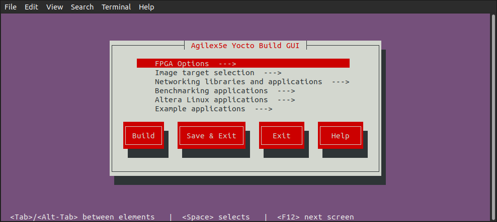
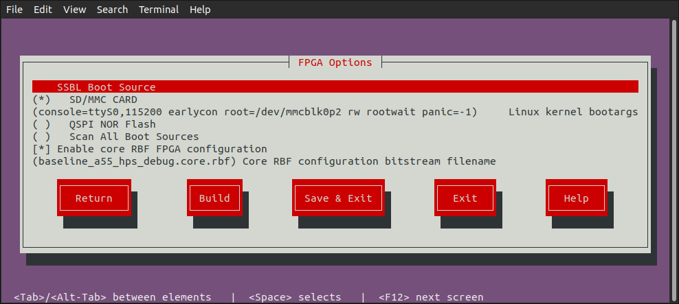
6. Go to FPGA Options screen and make any changes you desire:
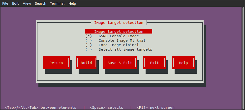
7. Go to Image Target Selection screen and select which images to be built:
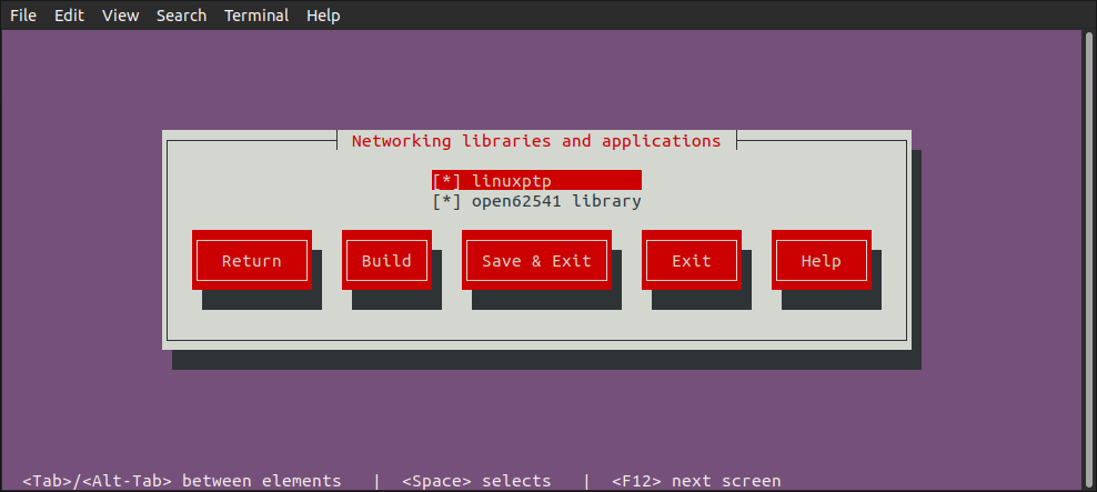
8. Go to Networking Libraries and Apllications screen and select desired options:
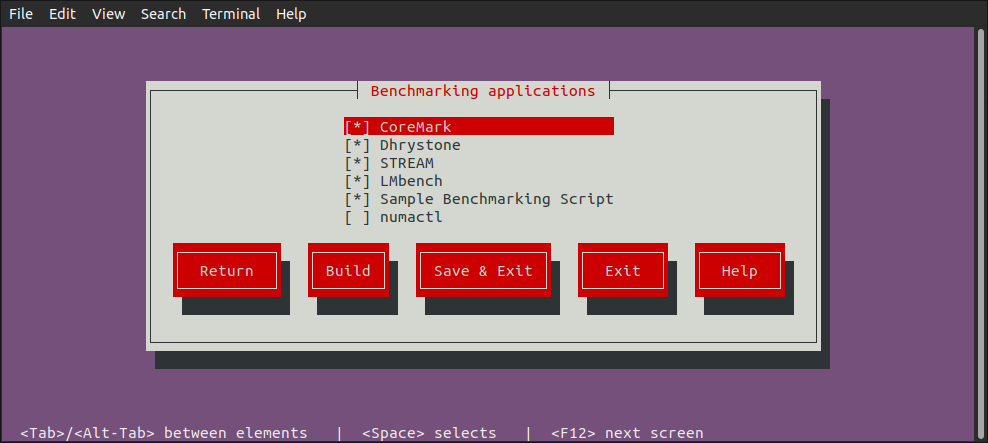
9. Go to Benchmarking Applications screen and select the desired applications:
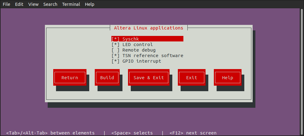
10. Go to Altera Linux Applications screen and select the desired applications:
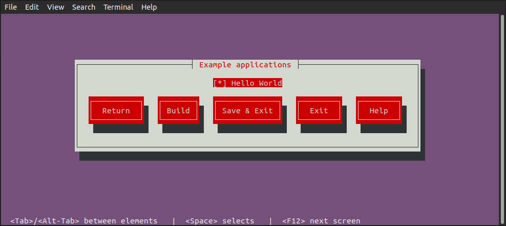
11. Go to Example Applications screen and select what you need:
12. Once you have selected all the options you want, you can clik the Build button to start the build process:
Build Kas Interactively
In addition to using kas build to build Yocto based on the kas.yml and kas menu to build Yocto based on Kconfig options selected from the text GUI, there is also the kas shell option, which allows you to build Yocto interactively.
1. Build the Quartus Design as mentioned before. Note the same Quartus Design is used for both booting from SD card and booting from QSPI.
2. Copy the core.rbf file to where Kas needs it to be:
cp $TOP_FOLDER/agilex5_soc_devkit_ghrd/install/binaries/ghrd.core.rbf \
   $TOP_FOLDER/agilex5_soc_devkit_ghrd/software/yocto_linux/meta-custom/recipes-fpga/fpga-bitstream/files/baseline_a55_hps_debug.core.rbf
3. Create an enter a new Python virtual environment, not to interfere with the current system Python packages:
cd $TOP_FOLDER/agilex5_soc_devkit_ghrd/software/yocto_linux
python3 -m venv venv --system-site-packages
source venv/bin/activate
pip install --upgrade pip
pip install kas
pip install --upgrade kas
pip install kconfiglib
4. You can optionally use kas menu to change settings, and at the end press the Save button instead of the Build button. This will save the custom configuration in the file .config.yaml.
5. Run kas shell, there are several options:
| Command | Description |
|---|---|
kas shell |
Use the configuration from the .config.yaml resulted from using kas menu |
kas shell kas.yml |
Use the default configuration for SD card boot |
kas shell kas.yml:qspi_boot_src.yml |
Use the default configuration for QSPI boot |
6. Use regular bitbake commands. For example to simply build the rootfs, use:
Using Benchmarking Applications
The HPS Baseline System Example Design provides you a set of Linux benchmarking applications that allow you to evaluate the performance of your system. These applications aim to evaluate areas such a CPUs performance and memory transfer performance among others.
You can control the inclusion/exclusion of each one of these applications individually using the KAS framework.
Option 1. Use the Kas menu
After you obtain the HPS Baseline System Example Design source content from the corresponding device HPS Baseline System Example Design repository and before you build Yocto with Kas, open the Kas menu with:
This opens the Kas graphical interface menu. Navigate to the Benchmarking applications option. This switches to a menu window that allows you to select the benchmarking applications that you want to include in your Linux file system.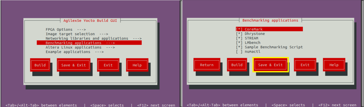
Once you complete the selection of the application, go to the Save and Exit option.
Option 2. Use the Kconfig Configuration file
Alternatively, you can add or remove the benchmarking applications by manually editing Kas configuration file software/yocto_linux/kas/gsrd/Kconfig. Each one of these applications is associated with a config that you can set to ‘y’ to include it or with ‘n’ to exclude this. An extract of this configuration file is shown next. After editing the file you must save it to keep these changes.
if GSRD_CONSOLE_IMAGE_BUILD
menu "Benchmarking applications"

config APP_COREMARK
    bool "CoreMark"
    default y
    help
      CoreMark - EEMBC benchmark for evaluating embedded CPU performance through lightweight core tests.

config BENCHMARK_APP_COREMARK
    string
    default "true" if APP_COREMARK
    default "false" if !APP_COREMARK
:
:
After you make your choose about the applications to be included or excluded, you can continue with the regular Kas Yocto Build.
NOTE: By default, all of the benchmarking applications are already enabled to be built and added in to the Linux file system. You still can use any of the 2 options above to change this default configuration. Also, it is very important to note that the benchmarking applications are only available when the target image is the gsrd-console-image . This means that you will not see them when the target is Console Image Minimal (console-image-minimal) nor Core Image Minimal (core-image-minimal). Please observe the implementation of the software/yocto_linux/kas/gsrd/Kconfig and the gsrd-console-image.bb recipe.
Once your binaries build finishes, you can proceed to program these in to your dev kit. After your board boots to Linux shell, you will see the benchmarking applications available in the file system under the /bin/ directory, meaning that you can actually exercise these applications from any path by just entering the application name similarly to how you can run any other Linux command.
The following table provides a brief description of the Benchmarking Scripts available as part of the HPS Baseline System Example Design:
| Application | Command | Description | Available by default |
|---|---|---|---|
| CoreMark | coremark | CoreMark is tailored for benchmarking embedded CPUs. It tests core functionalities such as list processing, matrix manipulation, state machines, and cyclic redundancy checks. The main metric used by CoreMark is iterations per second, which quantifies how many times the benchmark workload can be completed in one second. https://www.eembc.org/coremark/ |
Yes |
| Dhrystone | dhry | Dhrystone is a synthetic benchmark designed to measure CPU integer performance. It evaluates the processor's speed by executing non-floating-point instructions and reports results using the metric MIPS (Million Instructions Per Second), providing a standardized measure of general CPU throughput. https://github.com/sifive/benchmark-dhrystone | Yes |
| STREAM | stream stream.lmbench stream.mccalpin |
STREAM is a memory bandwidth benchmark that measures how quickly data can be transferred between memory and the CPU. It focuses on simple vector operations—Copy, Scale, Add, and Triad—to assess the sustainable memory transfer rates. Memory operations are done on a large data array (10000000 64-bit doubles) so that memory transfers do not involve the cache. The metric reported by STREAM is bandwidth in megabytes per second (MB/s). https://www.cs.virginia.edu/stream/ref.html | Yes |
| LMbench | lmbench-run bw_mem |
In LMbench, the bw_mem tool is specifically used to measure the memory bandwidth of a system by performing various types of memory operations. Among its commands, fcp (fast copy), fwr(fast write), and frd(fast read) execute memory operations on contiguous blocks of memory. LM Bench operates on variable data sizes; users can specify a data size that is less than the HPS cache size and bring in cache hits when the program executes memory operations. Each of these commands provides results in megabytes per second (MB/s), allowing users to analyze and compare the performance of memory read, write, and copy operations independently. https://lmbench.sourceforge.net/ | Yes |
| Sample Benchmark Script | run-hps-benchmarks | Altera provides this sample script that exercises automatically the different benchmarks applications supported. | Yes |
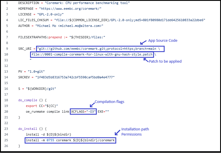
The applications are integrated into the Yocto build flow through recipes (.bb or .bbappend files). These recipes are located under the meta-altera-fpga/meta-altera-platform/recipes-benchmarking repository.
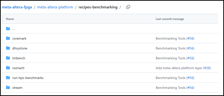
There is a Yocto recipe for each one of the application as you can see in the previous figure. In each one of the recipes you may find:
- The repository from which the application source code is obtained.
- The compilation flags needed.
- Any patch that need to be applied over the source code.
- Any required license file.
- The installation directory in the Linux file system in which the application binary will stored and the application binary permissions.
Note: Dhrystone and LMbench recipes already exist in meta-openembedded repository, so for these, only a .bbappend file is provided under meta-altera-fpga indicating the compilation flags needed.
The following figure shows an extract of the Coremark benchmarking application recipe.
The following table shows few examples of how the benchmarking applications can be used.
| Application | Example Description |
|---|---|
| CoreMark | Focus on single-threaded execution to highlight the performance of individual cores. Performance increases for multi-threaded execution is also predictable for CPU workloads (approximately proportional to number of cores). Example: taskset -c 0 “coremark 0x0 0x0 0x66 440000” CoreMark is executed by CPU0, with parameters: [seed1] [seed2] [seed3] [#iterations] seed1 is for linked list test, seed2 is for matrix manipulation test, seed3 is for state machine test. |
| Dhrystone | Focus on single-threaded execution to highlight the performance of individual cores. Performance increases for multi-threaded execution is also predictable for CPU workloads (approximately proportional to number of cores). Example: echo 1000000000 | taskset -c 0 dhry Dhrystone is executed by CPU0 passing 1000000000 as parameter indicating the number of Dhrystone iterations. |
| STREAM | Focus on single-threaded execution since all memory accesses are done through the same HPS-memory interface (no cache hits). Benchmarking runs will not significantly differ in multi-threaded execution when the memory interface is already fully utilized. Example: taskset -c 0 stream.mccalpin STREAM is executed by CPU0. By default, this application works on an array size of 10000000 bytes. |
| LMbench | Focus on single-threaded and multi-threaded execution. With multi-threaded execution, users can potentially see great performance increase if memory operations involve cache hits as well. Example: taskset -c 0 bw_mem -N 1000 -P 1 4K fcp LMbench is single-threaded executed for by CPU0 using the bw-mem memory bandwidth microbenchmark with parameters: -N [#iterations] -P [#processes] [memory size tested] [type of memory operation] For multi-threaded execution (4 processes): bw_mem -N 1000 -P 4 4K fcp |
| Sample Benchmark Script | The script receives as parameters the name of the application(s) that want to be executed. The script iterates over the cores enabled in the system (only one of the same family or CPU ID). Example: run-hps-benchmarks coremark dhrystone stream lmbench You can see the parameters provided to each one of the applications in the corresponding run_[application] function included in run-hps-benchmarks.sh script . The script produces an independent .log file with the results for each benchmarking application executed in a specific mode bound to a specific core. The output log file has the following format: [app_name]-[mode]-[#core].log |
Note: The taskset command in these examples enforces single-threaded execution on the CPU provided after the -c parameter.
Note: Additionally to the benchmark applications, the Linux HPS Baseline System Example Design also provides the numactl application. This application can be used together with the other benchmark applications and allow bind the application to a specific CPU (similarly to the taskset command) and to a local memory node. This application is not included by default in the HPS Baseline System Example Design. This includes commands like numactl, numademo and numastat. This is normally used to analyze memory latency and bandwidth by pinning workloads to specific sockets (for mor information refer to https://github.com/numactl). Here are some examples:
- numactl --show: Shows the current Non-Uniform Memory Access (NUMA) policy settings of a process.
- numastat: Monitors and displays per-node Non-Uniform Memory Access (NUMA) statistics.
- numactl -m 0 [benchmark app command]: Executes [benchmark app] application forcing all its memory allocations to come from NUMA node 0.
Update kernel.itb File
The kernel.itb file is a Flattattened Image Tree (FIT) file that includes the following components:
- Linux kernel.
- Board configurations* that indicate what components from the kernel.itb (Linux kernel, device tree and Phase 2 FPGA configuration bitstream) should be used for a specific board.
- Linux device tree*.
- Phase 2 FPGA configuration bitstream*.
* One or more of these components to support the different board configurations.
The kernel.itb is created from a .its (Image Tree Source file) that describes its structure. In the HPS Baseline System Example Design, the kernel.itb file is generated in the following directory. In this directory you can also find the .its files and all other the components needed to create the kernel.itb :
- $TOP_FOLDER/<gsrd-directory>/<project-directory>/software/yocto_linux/build/tmp/work/<device>-poky-linux/linux-socfpga-lts/<linux-branch>+git/linux-<device>-standard-build/
As an example of this path, for the Agilex 5 device you will find this directory as $TOP_FOLDER/a5ed065es-premium-devkit-oobe/baseline-a55/software/yocto_linux/build/tmp/work/agilex5e-poky-linux/linux-socfpga-lts/6.12.43-lts+git/linux-agilex5e-standard-build
If you want to modify the kernel.itb by replacing one of the component or modifying any board configuration, you can do the following:
-
Install mtools package in your Linux machine.
-
Go to the folder in which the kernel.itb is being created under the HPS Baseline System Example Design.
-
In the .its file, observe the components that integrates the kernel.itb identifying the nodes as indicated next:
images node:
- kernel node - Linux kernel defined with the data parameter in the node.
- fdt-X node - Device tree X defined with the data parameter in the node.
- fpga-X node - Phase 2 FPGA configuration bitstream .rbf defined with the data parameter in the node.configurations node:
- board-X node - Board configuration with the name defined with the description parameter. The components for a specific board configuration are defined with the kernel, fdt and fpga parameters. -
In this directory, you can replace any of the file components that integrate the kernel.itb, or you can also modify the .its to change the structure and components of the kernel.itb.
-
Finally, you need to re-generate the new kernel.itb running the following command in the same linux-
-standard-build/ directory.
Once that you have completed this procedure, you can use the new kernel.itb as needed. Some options could be:
- Use U-Boot to load this into the SDRAM board through TFTP to boot Linux or to write it to a flash device
- Directly update the flash image in your board (QSPI, SD Card, eMMC or NAND) from your working machine.
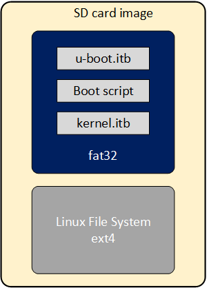
Update SD Card Image
As part of the Yocto HPS Baseline System Example Designbuild flow, the SD Card image is built for the SD Card boot flow. This image includes a couple of partitions. One of these partition (a FAT32) includes the U-Boot proper, the Distroboot boot script, U-Boot environment and the Linux .itb - which includes the Linux kernel image, the Linux device tree, the phase 2 FPGA configuration bitstream and board configuration (there may be several versions of these last 3 components). The 2nd partition (an EXT3 or EXT4 ) includes the Linux file system.
If you want to replace any the components or add a new item in any of these partitions, without having to run again the Yocto build flow.
This can be done through the wic script available on the Poky repository that is included as part of the HPS Baseline System Example Design build directory:
- $TOP_FOLDER/<gsrd-directory>/<project-directory>/software/yocto_linux/poky/scripts/wic
The wic command requires to be run in the Yocto build environment that can be setup as shown next in a Linux terminal:
cd $TOP_FOLDER/<gsrd-directory>/<project-directory>/software/yocto_linux/
source poky/oe-init-build-env build
The wic command allows you to inspect the content of a SD Card image, delete, add or replace any component inside of the image. This command is also provided with help support:
$ $TOP_FOLDER/<gsrd-directory>/<project-directory>/software/yocto_linux/poky/scripts/wic help

Creates a customized OpenEmbedded image.

Usage:  wic [--version]
        wic help [COMMAND or TOPIC]
        wic COMMAND [ARGS]

    usage 1: Returns the current version of Wic
    usage 2: Returns detailed help for a COMMAND or TOPIC
    usage 3: Executes COMMAND

COMMAND:

 list   -   List available canned images and source plugins
 ls     -   List contents of partitioned image or partition
 rm     -   Remove files or directories from the vfat or ext* partitions
 help   -   Show help for a wic COMMAND or TOPIC
 write  -   Write an image to a device
 cp     -   Copy files and directories to the vfat or ext* partitions
 create -   Create a new OpenEmbedded image
 :
 :
The following steps show you how to replace the kernel.itb file inside of the fat32 partition in a .wic image.
-
The wic ls command allows you to inspect or navigate over the directory structure inside of the SD Card image. For example you can observe the partitions in the SD Card image in this way.
# Here you can inspect the content a wic image see the 2 partitions inside of the SD Card image $ $TOP_FOLDER/<gsrd-directory>/<project-directory>/software/yocto_linux/poky/scripts/wic ls my_image.wic Num Start End Size Fstype 1 1048576 525336575 524288000 fat32 2 525336576 2098200575 1572864000 ext4 # Here you can naviagate inside of the partition 1 $ $TOP_FOLDER/<gsrd-directory>/<project-directory>/software/yocto_linux/poky/scripts/wic ls my_image.wic:1 Volume in drive : is boot Volume Serial Number is 8F65-ACE9 Directory for ::/ BOOTSC~1 UIM 2739 2011-04-05 23:00 boot.scr.uimg kernel itb 12885831 2011-04-05 23:00 uboot env 8192 2011-04-05 23:00 u-boot itb 938816 2011-04-05 23:00 4 files 13 835 578 bytes 509 370 368 bytes free -
The wic rm command allows you to delete any of the components in the selected partition. For example, you can delete the kernel.itb image from the partition 1(fat32 partition).
-
The wic cp command allows you to copy any new item or file from your Linux machine to a specific partition and location inside of the SD Card image. For example, you can copy a new kernel.itb to the partition 1.
NOTE: The wic application also allows you to modify any image with compatible vfat and ext* type partitions which also covers images used for eMMC boot flow.
Build and Exercise Roll Your Own Binaries
The "Roll Your Own" enables you to build a Linux system without using Yocto.
The key differences versus the Yocto/Kas build flow are:
- Each software component is built separately: ATF, U-Boot, Linux kernel, Linux root filesystem
- FPGA fabric is not configured
- The device tree from Linux kernel source code is used. This device tree does not enable IP from the FPGA fabric side
- Root filesystem is built with Toybox
- Root filesystem is used as initramfs. That makes it immutable, changes are not saved
- Binaries are not included, just build instructions
- Just the HPS Enablement Daughtercard, boot from SD card scenario is supported
HPS Enablement Board
Build SD Card Binaries
The overall build flow is presented in the following diagram:

The following diagram shows details on the flow used by the included roll your own build script:

The complete build instructions are presented below.
Prerequisites
The mtools are required in order to create the SD card image containing a single FAT partition. Install them on your Linux host. For Ubuntu you can use the following command:
Setup Environment
1. Create the top folder to store all the build artifacts:
sudo rm -rf agilex5_065b_ryo.sd
mkdir agilex5_065b_ryo.sd
cd agilex5_065b_ryo.sd
export TOP_FOLDER=`pwd`
Enable Quartus tools to be called from command line:
Build Quartus Design
cd $TOP_FOLDER
rm -rf agilex5_soc_devkit_ghrd && mkdir agilex5_soc_devkit_ghrd && cd agilex5_soc_devkit_ghrd
wget https://github.com/altera-fpga/agilex5e-ed-gsrd/releases/download/QPDS26.1_REL_GSRD_PR/a5ed065b-premium-devkit-oobe-baseline-a55.zip
unzip a5ed065b-premium-devkit-oobe-baseline-a55.zip
rm -f a5ed065b-premium-devkit-oobe-baseline-a55.zip
make baseline_a55-install
The following files are created:
$TOP_FOLDER/agilex5_soc_devkit_ghrd/install/binaries/baseline_a55.sof$TOP_FOLDER/agilex5_soc_devkit_ghrd/install/binaries/baseline_a55_hps_debug.sof$TOP_FOLDER/agilex5_soc_devkit_ghrd/install/binaries/ghrd.core.rbf
Build Software Components
1. Run the provided script to build the embedded software components: ATF, U-Boot, Linux Kernel & Device Tree, Linux rootfs:
The following relevant files are created in $TOP_FOLDER/agilex5_soc_devkit_ghrd/software/ryo_linux/build_output/:
sdcard.imgu-boot-socfpga/spl/u-boot-spl-dtb.hex
Build QSPI Image
cd $TOP_FOLDER/agilex5_soc_devkit_ghrd/software/ryo_linux/build_output/
rm -f output_file.hps.jic output_file.core.rbf
quartus_pfg \
-c  $TOP_FOLDER/agilex5_soc_devkit_ghrd/install/binaries/baseline_a55.sof output_file.jic \
-o device=MT25QU128 \
-o flash_loader=A5ED065BB32AE4S \
-o hps_path=u-boot-socfpga/spl/u-boot-spl-dtb.hex \
-o mode=ASX4 \
-o hps=1
The following file is created in $TOP_FOLDER/agilex5_soc_devkit_ghrd/software/ryo_linux/build_output/:
output_file.hps.jic
Refer to the Boot from SD Card section for details on how to write the SD card image and QSPI image, then boot to Linux. Note that the roll your own root filesystem is immutable, so any changes you may make will be discarded once you power cycle the board or reboot Linux. Also note that it is a simple, small root filesystem, without the sample applications or the webserver.
Notices & Disclaimers
Altera® Corporation technologies may require enabled hardware, software or service activation. No product or component can be absolutely secure. Performance varies by use, configuration and other factors. Your costs and results may vary. You may not use or facilitate the use of this document in connection with any infringement or other legal analysis concerning Altera or Intel products described herein. You agree to grant Altera Corporation a non-exclusive, royalty-free license to any patent claim thereafter drafted which includes subject matter disclosed herein. No license (express or implied, by estoppel or otherwise) to any intellectual property rights is granted by this document, with the sole exception that you may publish an unmodified copy. You may create software implementations based on this document and in compliance with the foregoing that are intended to execute on the Altera or Intel product(s) referenced in this document. No rights are granted to create modifications or derivatives of this document. The products described may contain design defects or errors known as errata which may cause the product to deviate from published specifications. Current characterized errata are available on request. Altera disclaims all express and implied warranties, including without limitation, the implied warranties of merchantability, fitness for a particular purpose, and non-infringement, as well as any warranty arising from course of performance, course of dealing, or usage in trade. You are responsible for safety of the overall system, including compliance with applicable safety-related requirements or standards. © Altera Corporation. Altera, the Altera logo, and other Altera marks are trademarks of Altera Corporation. Other names and brands may be claimed as the property of others.
OpenCL* and the OpenCL* logo are trademarks of Apple Inc. used by permission of the Khronos Group™.
Created: April 29, 2026